


T
roubleshooting
7-6
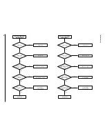
No Power (120 Voltage)
(Standby LED OFF)
PFD01 error?
PDS01 voltage
is missing?
Replace PICF1.
Replace fuse.
Check PRF10.
No
No
Yes
PICF1 Drain (pin 1)
voltage is missing?
Check 2d voltage.
No
Voltage exists in
PICF1-4?
Check PRF11 ~ PRF14.
Yes
No
Pulse is missing
in PICF1-5?
Replace PICF1.
Check feed back.
Yes
Yes
No
Yes
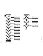
No Power (Free Voltage)
(Standby LED OFF)
PFD01 error?
PDS01 voltage
is missing?
Replace PQR11.
Replace fuse.
Check PDS01 ~ 04.
No
No
Yes
Collector of
PQR11 output normal
voltage?
Check 2'd voltage.
No
Operation of
PQR11 is normal?
Replace PQR12.
Yes
No
Switching operation
of PQR11 is normal?
Replace PQR11.
Check feed back.
Yes
Yes
No
Yes
Summary of Contents for DV-P313U
Page 9: ...Product Specification 3 2 MEMO ...
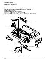
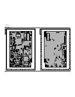
Page 19: ...5 6 Disassembly and Reaasembly 5 2 PCB Location Fig 5 6 PCB Location ...
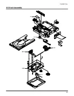
Page 34: ...8 1 8 Exploded View 8 1 Cabinet Assembly 8 2 Deck Assembly Page 8 2 8 3 ...
Page 36: ...Exploded Views 8 3 8 2 Deck Assembly 107 H220 H106 H207 H200 H210 ...
Page 37: ...Exploded Views 8 4 MEMO ...
Page 41: ...Block Diagram 10 2 MEMO ...
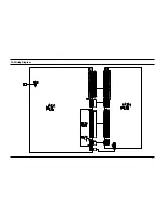
Page 42: ...11 1 11 PCB Diagrams 11 2 11 3 11 4 11 4 11 1 Main 11 2 Jack 11 3 Deck 11 4 Housing ...
Page 43: ...PCB Diagrams 11 2 11 1 Main COMPONENT SOLDER SIDE ...
Page 44: ...PCB Diagrams 11 3 11 2 Jack ...
Page 45: ...PCB Diagrams 11 4 11 3 Deck 11 4 Housing ...
Page 46: ...12 1 12 Wiring Diagram ...
Page 47: ...Wiring Diagram 12 2 MEMO ...
Page 49: ...Schematic Diagrams 13 2 13 1 Power ...
Page 50: ...Schematic Diagrams 13 3 13 2 AV Decoder Main Micom Key KEY ...
Page 51: ...Schematic Diagrams 13 4 13 3 Servo ...
Page 52: ...Schematic Diagrams 13 5 OPTION 13 4 Video ...
Page 53: ...Schematic Diagrams 13 6 OPTION OPTION 13 5 Audio ...
Page 54: ...Schematic Diagrams 13 7 OPTION OPTION 13 6 Front Micom VFD Display ...
Page 55: ...Schematic Diagrams 13 8 HOUSING PCB 13 7 Deck ...