background image

9

English

NOTE:

Turn the selector lever (do not push the button) to
check if it is completely locked and make sure that
it does not turn.

5.

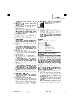
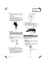
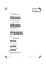
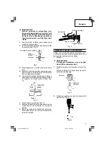
Warming up (Fig. 8)
The grease lubrication system in this unit may
require warming up in cold regions.
Position the end of the bit so makes contact with
the concrete, turn on the switch and perform the
warming up operation. Make sure that a hitting
sound is produced and then use the unit.

CAUTION:
When the warming up operation is performed,
hold the side handle and the main body securely
with both hands to maintain a secure grip and be
careful not to twist your body by the jammed drill
bit.

6.

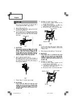
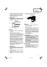
How to use the drill bit (taper shank) and the taper
shank adaptor.

(1)

Install drill bit with taper shank in the taper shank
adaptor. (Fig. 9)

(2)

Turn the power on and drill a base hole.

(3)

After cleaning out dust with a syringe, attach the
plug to the anchor tip and drive in the anchor with
a manual hammer.

(4)

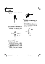
To remove the drill bit with taper shank, insert a
cotter into the slot of the taper shank adaptor, place
supports under the Rotary Hammer and tap the
cotter with a manual hammer. (Fig. 10)

7.

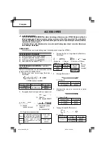
Using the stopper (Fig. 11)

(1)

Loosen the wing bolt, and insert the stopper into
the mounting hole on the side handle.

(2)

Adjust the stopper position according to the depth
of the hole and tighten the wing bolt securely.

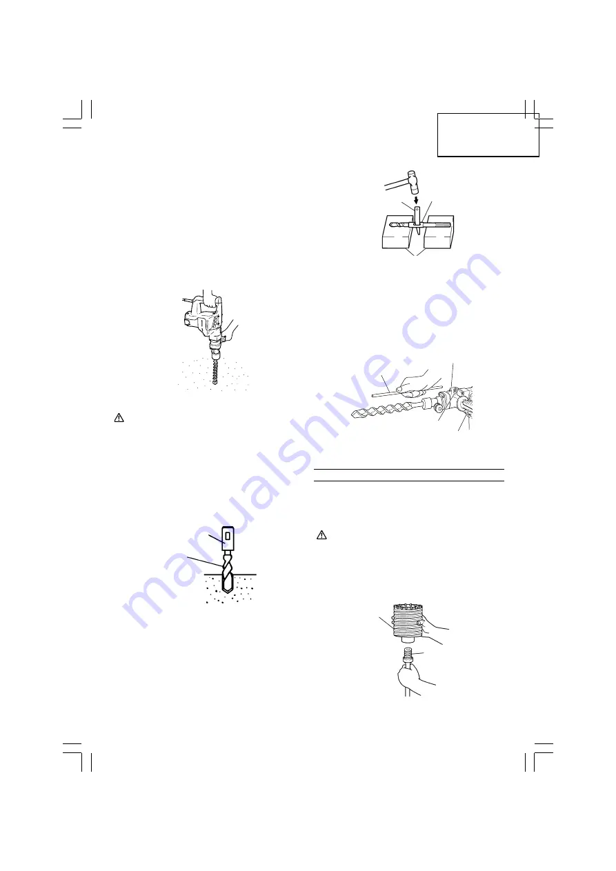
HOW TO USE THE CORE BIT

When boring penetrating large hole use the core bit. At
that time use with the center pin and the core bit shank
provided as optional accessories.
1.

Mounting

CAUTION:
Be sure to turn power OFF and disconnect the plug
from the receptacle.

(1)

Mount the core bit to the core bit shank. (Fig. 12)
Lubricate the thread of the core bit shank to
facilitate disassembly.

Fig. 8

Fig. 9

Drill bit
(Taper shank)

Taper shank adaptor

Fig. 10

Fig. 12

Fig. 11

Taper shank
adaptor

Cotter

Support

Core bit

Core bit shank

Stopper

Mounting hole

Wing bolt

Side handle

01Eng_DH38YE2_US

4/21/10, 4:26 PM

9

Summary of Contents for DH 38YE2

Page 1: ...or serious bodily injury This manual contains important information about product safety Please read and understand this manual BEFORE operating the power tool Please keep this manual available for other users and owners before they use the power tool This manual should be stored in safe place INSTRUCCIONES DE SEGURIDAD Y MANUAL DE INSTRUCCIONES ADVERTENCIA La utilización INAPROPIADA O PELIGROSA d...

Page 2: ...R 17 DESCRIPTION FONCTIONNELLE 18 NOM DES PARTIES 18 SPECIFICATIONS 18 Page ASSEMBLAGE ET FONCTIONNEMENT 19 APPLICATIONS 19 AVANT L UTILISATION 19 UTILISATION 19 COMMENT UTILISER LA COURONNE 21 ENTRETIEN ET INSPECTION 22 ACCESSOIRES 24 ACCESSOIRES STANDARD 24 ACCESSOIRES SUR OPTION 24 LISTA DES PIÈCES 38 Página INFORMACIÓN IMPORTANTE SOBRE SEGURIDAD 26 SIGNIFICADO DE LAS PALABRAS DE SEÑALIZACIÓN 2...

Page 3: ...rded power tool or battery operated cordless power tool 1 Work area safety a Keep work area clean and well lit Cluttered or dark areas invite accidents b Do not operate power tools in explosive atmospheres such as in the presence of flammable liquids gases or dust Power tools create sparks which may ignite the dust of fumes c Keep children and bystanders away while operating a power tool Distracti...

Page 4: ...ool Power tools are dangerous in the hands of untrained users e Maintain power tools Check for misalignment or binding of moving parts breakage of parts and any other condition that may affect the power tool s operation If damaged have the power tool repaired before use Many accidents are caused by poorly maintained power tools f Keep cutting tools sharp and clean Properly maintained cutting tools...

Page 5: ...er tool be dropped or struck against hard materials inadvertently it may be deformed cracked or damaged 20 Do not wipe plastic parts with solvent Solvents such as gasoline thinner benzine carbon tetrachloride and alcohol may damage and crack plastic parts Do not wipe them with such solvents Wipe plastic parts with a soft cloth lightly dampened with soapy water and dry thoroughly 21 ALWAYS wear eye...

Page 6: ...erate or attempt any maintenance on the tool unless you have first read and understood all safey instructions contained in this manual Some illustrations in this Instruction Manual may show details or attachments that differ from those on your own power tool NAME OF PARTS Housing Switch trigger Side handle Handle Nameplate Tail cover Set screw Under the Tail cover Selector lever Brush cap Inside t...

Page 7: ...Weight 14 1 lbs 6 4 kg ASSEMBLY AND OPERATION APPLICATIONS Rotation and hammering function 䡬 Drilling anchor holes 䡬 Drilling holes in concrete Hammering function only 䡬 Demolishing concrete chipping digging and squaring by applying optional accessories PRIOR TO OPERATION 1 Power source Ensure that the power source to be utilized conforms to the power source requirements specified on the product n...

Page 8: ...ctor lever during motor rotation the tool can start to rotate abruptly resulting in unexpected accidents Be sure to switch the selector lever when the motor is at a complete stop 1 Switching to rotation hammering a Push the button release lock and turn the selector lever clockwise b Align of the selector lever and of the lever holder as illustrated in Fig 6 c Release the button to lock the selecto...

Page 9: ...ch the plug to the anchor tip and drive in the anchor with a manual hammer 4 To remove the drill bit with taper shank insert a cotterintotheslotofthetapershankadaptor place supports under the Rotary Hammer and tap the cotter with a manual hammer Fig 10 7 Using the stopper Fig 11 1 Loosen the wing bolt and insert the stopper into the mounting hole on the side handle 2 Adjust the stopper position ac...

Page 10: ...e to left or right so that it does not fall even if it faces downward Fig 14 2 How to bore Fig 15 1 Connect the plug to the receptacle 2 A spring is installed in the center pin Push it lightly to the wall or the floor straight Connect all over the surface of the core bit tip and start operating 3 When boring about 3 16 5 mm in depth the position of the hole will establish Bore after that removing ...

Page 11: ...ts Since use of a dull tool will cause motor malfunctioning and degraded efficiency replace the drill bit with a new one or resharpening without delay when abrasion is noted 2 Inspecting the screws Regularly inspect all screws and ensure that they are properly tightened Should any of the screws be loose retighten them immediately WARNING Using this Rotary Hammer with loosen screws is extremely dan...

Page 12: ...erToolsareconstantlybeingimproved and modified to incorporate the latest technological advancements Accordingly some parts may be changed without prior notice ACCESSORIES WARNING ALWAYS use Only authorized HITACHI replacement parts and accessories NEVER use replacement parts or accessories which are not intended for use with this tool Contact HITACHI if you are not sure whether it is safe to use a...

Page 13: ...ubject to change without any obligation on the part of the HITACHI 1 Bull point Overall length Code No 12 300 mm 985383 1 Cold chisel Overall length Code No 12 300 mm 985381 18 460 mm 985382 1 Cutter Overall length Width Code No 12 300 mm 1 1 2 38 mm 985384 2 50 mm 985385 1 Scoop Code No 985386 Code No 320859 Code No 318085 01Eng_DH38YE2_US 4 21 10 4 26 PM 13 ...

Page 14: ...tructions Tout manquement à observer ces avertissements et instructions peut engendrer des chocs électriques des incendies et ou des blessures graves Conservez tous les avertissements et toutes les instructions pour vous y référer ultérieurement Le terme outil électrique utilisé dans les avertissements se réfère aux outils électriques câblé ou aux outils à piles sans fil 1 Sécurité de l aire de tr...

Page 15: ...peuvent se prendre dans les pièces mobiles g En cas de dispositifs destinés au raccordement d installations d extraction et de recueil de la poussière veiller à ce qu ils soient correctement raccordés et utilisés L utilisation d un dispositif de collecte de la poussière peut réduire les dangers associés à la poussière 4 Utilisation et entretien d un outil électrique a Ne pas forcer sur l outil éle...

Page 16: ...utilisé par des enfants des personnes non familiarisées avec son fonctionnement ou un personnel non autorisé 12 Maintenir toutes les vis tous les boulons et les couvercles fermement en place Maintenir toutes les vis tous les boulons et les couvercles fermement montés Vérifier leurs conditions périodiquement 13 Nepasutiliserlesoutilsmotoriséssilerevêtement de plastique ou la poignée est fendu Des f...

Page 17: ...icitéconnectésàl outilmotoriséàpartirducadre extérieur manipulé par l utilisateur C est pourquoi le symbole ou les mots Double insulation double isolation apparaissent sur l outil motorisé ou sur la plaque signalétique Bien que ce système n ait pas de mise à terre extérieure il est quand même nécessaire de suivre les précautions de sécurité électrique données dans ce mode d emploi y compris de ne ...

Page 18: ...er des détails ou des accessoires différents de ceux de l outil motorisé utilisé NOM DES PARTIES SPECIFICATIONS Moteur Moteur série monophasé à collecteur Source d alimentation Secteur 120 V 60 Hz monophasé Courant 8 4 A Capacité Mèche 1 1 2 38 mm Couronne 4 13 64 105 mm Vitesse sans charge 620 min Vitesse de percussion à pleine charge 2 800 min Poids 14 1 lbs 6 4 kg Fig 1 Carter Interrupteur Poig...

Page 19: ...la source d alimentation qui doit être utilisée est conforme à la source d alimentation requise spécifiée sur la plaque signalétique du produit 2 Interrupteur d alimentation S assurer que l interrupteur est sur la position OFF arrêt Si la fiche est connectée sur une prise alors que l interrupteur est sur la position ON marche l outil motorisé démarrera immédiatement risquant de causer de sérieuses...

Page 20: ...tion Fig 7 Cache inférieur Sélecteur Bouton Cache inférieur Bouton Fig 6 Sélecteur Fig 5 REMARQUE Tourner le sélecteur ne pas appuyer dessus pour voir s il est bien verrouillé à fond et s assurer qu il ne tourne pas 4 Burinage et découpures en percussion PRECAUTION 䡬 Si l on règle le sélecteur pendant la rotation du moteur l outil risque de se mettre brusquement en marche et de provoquer des bless...

Page 21: ... queue conique et le raccord de queue conique 1 Installer la mèche à queue conique dans le raccord de queue conique Fig 9 2 Mettre l appareil sous tension et percer un trou de base 3 Après avoir retirer la poussière avec une seringue fixer le mandrin à la pointe du sabot et l enfoncer dans le sabot avec un marteau 4 Pour retirer la mèche à queue conique insérer une clavette dans la fente du raccor...

Page 22: ...onne Cela aura pour effet de desserrer le filetage et on pourra retirer la couronne Fig 16 ENTRETIEN ET INSPECTION AVERTISSEMENT S assurer de mettre l interrupteur d alimentation sur la position OFF et de déconnecter la fiche de la prise secteur avant l entretien et l inspectio 1 Contrôle du foret de perçage Etant donné que l utilisation d une mèche usée entraînera un mauvais fonctionnement du mot...

Page 23: ...cle du carter et essuyer la graisse à l intérieur Fig 18 2 Appliquer 2 0 oz 60 g de graisse pour marteau électriqueHitachiA accessoiresuroption entube au carter Limite d usure No du balai en carbone 0 28 7 mm 0 67 17 mm 43 Fig 17 3 Après avoir fait le plein de graisse installer fermement le couvercle du carter REMARQUE La graisse pour marteau électrique Hitachi A est du type à viscosité faible 6 E...

Page 24: ...3 1 Ciseau à froid Longueur totale No de code 12 300 mm 985381 18 460 mm 985382 1 Fraise Longueur totale Largeur No de code 12 300 mm 1 1 2 38 mm 985384 2 50 mm 985385 Cône A Cône B No de code 985377 No de code 985378 La raccord de queue conique en forme cône A ou cône B est fournientantqu accessoiresur option mais la mèche correspondante n est par fournie ACCESSOIRES AVERTISSEMENT TOUJOURS utilis...

Page 25: ...ingue pour enlever déchets REMARQUE Les spécifications sont sujettes à modification sans aucune obligation de la part de HITACHI 1 Bourroir No de code 985386 No de code 320859 No de code 318085 02Fre_DH38YE2_US 4 21 10 4 43 PM 25 ...

Page 26: ...s advertencias e instrucciones podría producirse una descarga eléctrica un incendio y o daños graves Guarde todas las advertencias e instrucciones para futura referencia El término herramienta eléctrica en las advertencias hace referencia a la herramienta eléctrica que funciona con la red de suministro con cable o a la herramienta eléctrica que funciona con pilas sin cable CONSERVE ESTAS INSTRUCCI...

Page 27: ...nectados y se utilizan adecuadamente La utilización de un sistema de recogida de polvo puede reducir los riesgos relacionados con el polvo 4 Utilización y mantenimiento de las herramientas eléctricas a No fuerce la herramienta eléctrica Utilice la herramienta eléctrica correcta para su aplicación La herramienta eléctrica correcta trabajará mejor y de forma más segura si se utiliza a la velocidad p...

Page 28: ...operación de la herramienta utilicen ésta 12 Mantenga todos los tornillos pernos y cubiertas firmemente fijados en su lugar Mantenga todos los tornillos pernos y cubiertas firmemente montados Compruebe periódicamente su condición 13 No utilice herramientas eléctricas si la carcasa o la empuñadura de plástico está rajada Las rajas en la carcasa o en la empuñadura de plástico pueden conducir a desca...

Page 29: ...lotanto en la herramienta eléctrica o en su placa de características aparecen el símbolo o las palabras Double insulation aislamiento doble Aunque este sistema no posee puesta a tierra externa usted deberá seguir las precauciones sobre seguridad eléctrica ofrecidas en este Manual de instrucciones incluyendo la no utilización de la herramienta eléctrica en ambientes húmedos Para mantener efectivo e...

Page 30: ...seguridad y mantener esta herramienta eléctrica NUNCA haga funcionar ni efectúe el mantenimiento de la herramienta antes de leer y comprender todas las instrucciones de seguridad contenidas en este manual Algunas ilustraciones de este Manual de Instrucciones pueden mostrar detalles o accesorios diferentes a los de la propia herramienta eléctrica NOMENCLATURA Fig 1 Carcase Interruptor disparador Ma...

Page 31: ...s del producto 2 Interruptor de alimentación Cerciórese de que el interruptor de alimentación esté en la posición OFF Si enchufase el cable de alimentación en un tomacorriente de la red con el interruptor en ON la herramienta eléctrica comenzaría a funcionar inmediatamente lo que podría provocar lesiones serias 3 Cable prolongador Cuando el área de trabajo esté alejada de la fuente de alimentación...

Page 32: ...adrar en el hormigón u otro material semejante puede pasar que al atascarse la barrena el cuerpo del martillo gire en dirección opuesta Asegurarse entonces de que el mango principal y el lateral están bien empuñados durante el uso de esta herramienta 2 Cómo tallar o demoler Fig 5 Aplicando la punta de la herramienta en posición de tallar o demoler hacer funcionar el martillo perforador aplicando s...

Page 33: ...sacar la broca con la barrena ahusada introduzca una chaveta en la ranura del adaptador de barrena ahusada ponga apoyos debajo del martillo perforador y golpee la chaveta con un martillo de mano Fig 10 7 Uso del tope Fig 11 1 Afloje el perno de palomilla e inserte el tope en el orificio de montaje de la empuñadura lateral 2 Ajuste la posición del tope en función de la profundidad del orificio y aj...

Page 34: ... central y la placa guía poner el interruptor en la posición de apagado OFF y desconectar el enchufe de la toma de alimentación 3 Desmontaje Fig 16 Como otro método quitar la espiga de la barrena tubular del martillo perforador y golpear fuertemente la cabeza de la espiga de la barrena tubular dos o tres veces con un martillo sujetanto la punta de la barrena La parte roscada se aflojará y la barre...

Page 35: ...so requiere cambiar la grasa proceder como sigue Período de cambio de grasa Luego de adquirir la herramienta cambiarle la grasa cada 6 meses de uso Consultar para ello al centro de servicio HITACHI autorizado Procedimiento de cambio de grasa Rellenado de grasa PRECAUCIÓN Antes de rellenar de grasa desconectar el aparato y desenchufarlo del tomacorriente 1 Quitar la cubierta del cigüeñal y limpiar ...

Page 36: ...se llamar a HITACHI 1 800 59 TOOLS 1 Perforación por orificio Rotación Martilleo 1 Barrena espiga ranurada 2 Perforación de orificio de anclaje Rotación martilleo 3 Cortadora Núm de código 944477 Diámetro externo Longitud total Núm de código 1 25 mm 16 400 mm 985375 1 1 2 38 mm 985376 MODIFICACIONES Hitachi Power Tools introduce constantemente mejoras y modificaciones para incorporar los últimos a...

Page 37: ...cificaciones están sujetas a cambio sin ninguna obligación por parte de HITACHI 1 Cortadora Largo total Anchura Núm de código 12 300 mm 1 1 2 38 mm 985384 2 50 mm 985385 Núm de código 320859 Núm de código 318085 1 Cortafrio Largo total Núm de código 12 300 mm 985381 18 460 mm 985382 1 Cuchara Núm de código 985386 03Spa_DH38YE2_US 4 21 10 4 39 PM 37 ...

Page 38: ...8 30 31 32 33 34 35 29 36 37 38 39 40 41 43 45 46 47 48 49 50 51 52 53 54 55 56 57 58 59 60 62 61 62 63 66 67 68 69 70 71 72 73 74 46 75 79 82 83 84 76 78 77 80 81 85 88 89 90 86 91 93 63 92 91 96 95 94 100 101 99 98 102 87 64 501 42 502 19 44 503 03Spa_DH38YE2_US 4 21 10 4 39 PM 38 ...

Page 39: ...50 WASHER 1 51 WASHER A 1 52 GEAR HOLDER 1 53 SPRING C 10 54 NEEDLE 10 55 SECOND GEAR 1 56 SPACER 1 57 BALL BEARING 629VVC2PS2L 1 58 BEARING WASHER C 1 59 SEAL LOCK HEX SOCKET HD BOLT M6 x 20 2 60 SEAL LOCK HEX SOCKET HD BOLT M6 x 45 4 61 CRANK COVER 1 62 HITACHI LABEL 2 63 HEX SOCKET HD BOLT W FLANGE M5 x 16 6 64 CYLINDER O RING B 1 65 CRANK CASE 1 66 SEAL PACKING 1 67 RETAINING RING FOR D10 SHAF...

Page 40: ...e la fréquence d exécution de ce genre de travail Pour réduire l exposition à ces produits chimiques travailler dans un lieu bien ventilé et porter un équipement de protection agréé par exemple un masque anti poussière spécialement conçu pour filter les particules microscopiques ADVERTENCIA Algunos polvos creados por el lijado mecánico el aserrado el esmerilado el taladrado y otras actividades de ...

Reviews: