


--- 25 ---
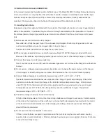
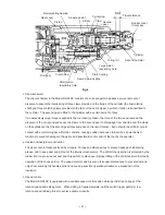
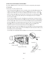
(1) Disassembly of the striking mechanism section
Push in the Second Hammer
[26]
with a drill bit or a screwdriver. Remove the Striker
[34]
chucked by O-ring
(C)
[31]
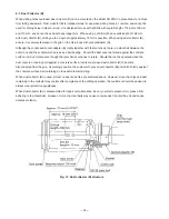
. The Change Lever
[19]
is positioned "Rotation Only" ( mark) as shown in Fig. 11. Remove the
Tapping Screw D2.6
[17]
and turn the Change Lever
[19]
by approximately 200
û
clockwise. Adjust the " "
mark of the Change Lever
[19]
to the center of the notch on the gear cover. Ply out the Change Lever
[19]
at
this position. Remove the Tapping Screw (W/Flange) D5 x 25 (Black)
[9]
from the Gear Cover
[10]
and
remove the Gear Cover
[10]
.
The Inner Cover Ass'y
[39]
and Housing (A). (B) Set
[67]
are loosely fitted together. Attempting to pull them
out first could cause the Armature and Pinion Ass'y
[55]
to be pulled out at the same time, causing damage to
the Carbon Brushes
[61]
. Remove from the end of the Second Shaft
[41]
, and turn the Second Shaft
[41]
so
that the Piston
[36]
moves to its maximum upper position (inner cover side). The arm of the Reciprocating
Bearing
[46]
can then be disconnected from the Piston Pin
[45]
, and the Second Shaft
[41]
and the
components mounted on it can be removed from the Inner Cover Ass'y
[39]
as a unit.
With a bearing puller, remove the First Gear
[48]
from the Second Shaft
[41]
. Then take off the Reciprocating
Bearing
[46]
. At this time, carefully note that the First Gear
[48]
must be aligned with and press-fitted onto the
9 mm diameter end of the Second Shaft
[41]
.
The Clutch
[44]
, Clutch Spring
[43]
and Washer (B)
[42]
can then be removed from the Second Shaft
[41]
.
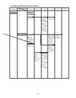
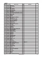
9. PRECAUTIONS IN DISASSEMBLY AND REASSEMBLY
The numbers in
[Bold]
correspond to the item numbers in the Parts List and exploded assembly diagrams.
9-1. Disassembly
Tapping Screws D2.6
[17]
Fig. 11
Change Lever
[19]
Gear Cover
[10]
Notch
Viewed from "A"
Notch
A