-5-
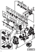
Fig. 6 • Reassembly of the gear cover and cylinder ass’y
2. Reassembly of the gear cover and cylinder ass’y
(1) Mount the Second Gear
[18]{18}
, Spring (A)
[17]{17}
, and Washer
[16]{16}
on the Cylinder
[20]{20}
ass’y and fix them with the Retaining Ring for D25 Shaft
[15]{15}
. Mount the Damper
[26]{26}
, Thrust
Washer (A)
[27]{27}
, and Thrust Washer (B)
[28]{28}
from the rear end of the Cylinder
[20]{20}
. Then,
push this ass’y into the Gear Cover
[9]{9}
as far as it will go.
NOTE: Be sure to mount the parts in the correct order as shown in Fig. 6.
(2) Mount the O-ring
[12]{12}
to the Change Lever
[11]{11}
and put it in the hole on the Gear Cover
[9]{9}
.
Insert the Stopper
[13]{13}
into the groove inside the Change Lever
[11]{11}
. Then, push the Change
Lever
[11]{11}
in the hole of the Gear Cover
[9]{9}
as far as it will go.
NOTE: Push the Change Lever [11]{11} in the Gear Cover [9]{9} without tilting so that the O-ring
[12]{12} is not twisted.
(3) Set the Change Lever
[11]{11}
to the "Ro Hammering" ( mark) position. Tighten the Machine
Screw M4 x 5
[14]{14}
to fix the Change Lever
[11]{11}
to the Gear Cover
[9]{9}
.
(4) Mount the Holder Spring
[7]{7}
, Holder Plate
[6]{6}
, and Steel Ball D7.0
[19]{19}
to the tip of the Cylinder
[20]{20}
. Mount the Ball Holder
[5]{5}
to the Grip
[4]{4}
and mount it to the Cylinder
[20]{20}
. Then,
mount the Stopper Ring
[3]{3}
and Front Cap
[2]{2}
to the Cylinder
[20]{20}
.
[27]{27}
[28]{28}
[26]{26}
[17]{17}
[16]{16}
[15]{15}
[18]{18}
[11]{11}
[13]{13}
[14]{14}
[7]{7}
[6]{6}
[5]{5}
[5]{5}
[3]{3}
[4]{4}
[2]{2}
Та
ше
в
-
Га
лв
ин
г
ОО
Д
www.tashev-galving.com


