background image

ENGLISH-16

O

O

O

O

P

P

P

P

E

E

E

E

R

R

R

R

A

A

A

A

T

T

T

T

II

II

O

O

O

O

N

N

N

N

S

S

S

S


((

((

c

c

c

c

o

o

o

o

n

n

n

n

tt

tt

ii

ii

n

n

n

n

u

u

u

u

e

e

e

e

d

d

d

d

))

))

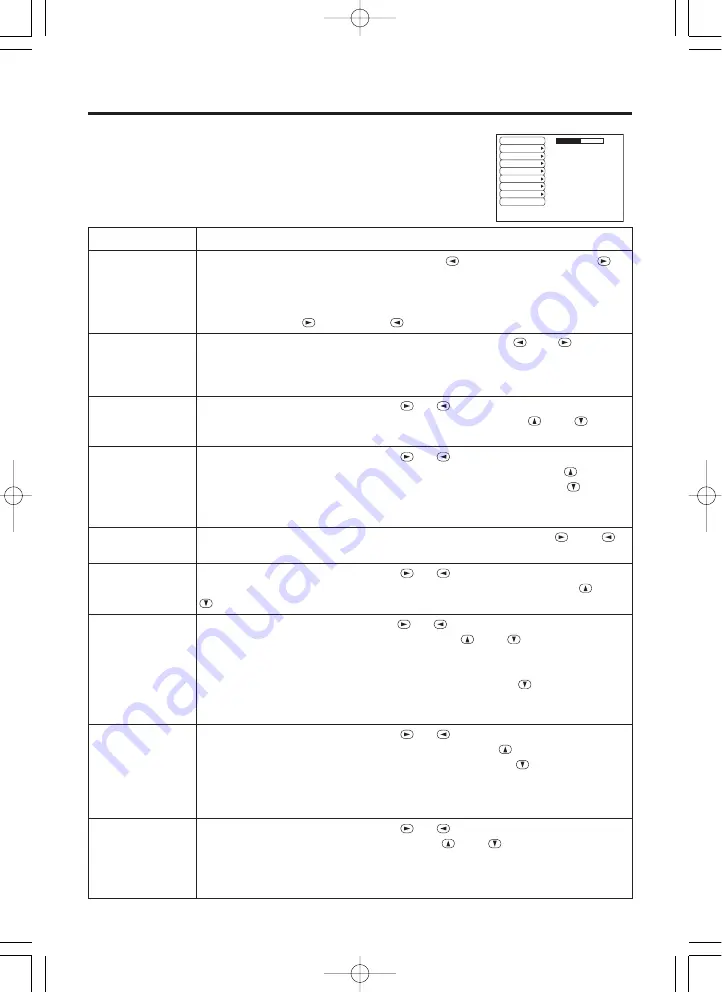
No Signal Menu

The same adjustments and settings are available as with the Image and
Options menus when the MENU button is pressed during display of the
“NO INPUT IS DETECTED ON ***” or “SYNC IS OUT OF RANGE
ON ***” message while no signal is received.

Table 8. No Signal Menu

VOLUME

BLANK

MIRROR

START UP

MENU COLOR

LANGUAGE

AUTO OFF

SYNC ON G

WHISPER

16

Item

Description

VOLUME

Volume Adjustment:

Reduce VOLUME 

Increase VOLUME 

• When this function is used, audio input is automatically switched to video. The
audio input can be switched by moving the DISK PAD left and right during the
display of the volume adjustment bar. The volume adjustment bar is displayed by
pressing VOLUME 

or VOLUME 

button.

BLANK

Select Blank Screen Color:

Select the color with the 

and 

buttons.

• The image is cleared and the entire screen is displayed in the selected color,
when BLANK mode is set with BLANK ON, or when there is no signal for 5
minutes.

MIRROR

Operation Start/Stop:

Press the 

or 

button.

Select Mirror Status:

Select the mirror status with the 

and 

buttons.

START UP

Operation Start/Stop:

Press the 

or 

button.

Setup Initial Screen Display:

Select the TURN ON with the 

button.

Clear Initial Screen Display:

Select the TURN OFF with the 

button.

• Note that if TURN OFF is selected the blank screen is displayed in blue when
there is no signal.

MENU COLOR

Select Menu Background Color:

Select the color with the 

and 

buttons.

LANGUAGE

Operation Start/Stop:

Press the 

or 

button.

Select Menu Display Language:

Select the language with the 

and

buttons.

AUTO OFF

Operation start/stop:

Press the 

or 

button.

Set AUTO OFF:

Set 1~99 minutes with the 

and 

buttons. The

system automatically enters the standby mode when a signal is not
received for the set time.

Clear AUTO OFF:

Select the STOP (0 min.) with the 

button. When

the STOP is selected the system does not enter the standby mode even
if no signal is received.

SYNC ON G

Operation Start/Stop:

Press the 

or 

button.

SYNC ON G Valid:

Select the TURN ON with the 

button.

SYNC ON G Invalid:

Select the TURN OFF with the 

button.

• May not be displayed correctly with some input signals when the SYNC ON G is
valid. In such cases, remove the signal connector so that no signal is received,
set the SYNC ON G to invalid, and reconnect the signal.

WHISPER

Operation Start/Stop:

Press the 

or 

button.

Set / Crear WHISPER Mode: 

Press the 

and 

button.When the

WHISPER is selected, the WHISPER mode is active. In the WHISPER
mode, acoustic moise level from the unit is reduced, and brightness
level on screen is a little lower.

01CP-SX5500W02    01.10.24  1:39  PM    ページ 16

Summary of Contents for CP-SX5500

Page 1: ...oler leggere attentamente il manuale d sitruzioni in modo tale da poter comprendere quanto riportato ai fini di un corretto utilizzo del proiettore MANUAL DE USUARIO Lea cuidadosamente este manual del usuario para poder utilizar corretamente el producto GEBRUIKSAANWIJZNG Lees voor het qebruik alstublieft deze handleiding aandachtig door om volledig profijt te hebben van de uitgebreide mogelijkhede...

Page 2: ...sage 20 Table 10 Indicator Message 21 Table 11 Symptom 22 Table 12 Specifications 23 For TECHNICAL and REGULATORY NOTICE see the end of this manual The information in this manual is subject to change without notice The manufacturer assumes no responsibility for any errors that may appear in this manual The reproduction transmission or use of this document or contents is not permitted without expre...

Page 3: ...eitung zugunsten der korrekten Bedienung aufmerksam MANUEL D UTILISATION Nous vous recommandons de lire attentivement ce manuel pour bien assimiler le fonctionnement de l appareil MANUALE D ISTRUZIONI Vi preghiamo voler leggere attentamente il manuale d sitruzioni in modo tale da poter comprendere quanto riportato ai fini di un corretto utilizzo del proiettore MANUAL DE USUARIO Lea cuidadosamente ...

Page 4: ...UDIO IN RGB OUT CONTROL RGB IN DVl USB COMPONENT VIDEO CR PR VIDEO S VIDEO R L MONO RGB1 DVl RGB2 CB PB Y 3 1 2 2 3 1 LAMP TEMP STANDBY ON INPUT SELECT RGB VIDEO RESET MENU KEYSTONE 1 2 3 TEMP Indicator LAMP Indicator STANDBY ON Button STANDBY ON Indicator VIDEO Button RGB Button KEYSTONE Button MENU Button RESET Button Remote Control Sensor Lens AC Inlet to Power Cord Power Switch Lens Cap Contro...

Page 5: ...ARECCHIO LASER DI CLASSE 2 RAYONNEMENT LASER NE PAS REGARDER DANS LE FAISCEAU APPAREIL A LASER DE CLASSE 2 LASER STRAHLUNG NICHT IN DEN STRAHL BLICKEN LASER KLASSE2 MANUFACTURED PLACE OF MANUFACTURER A MADE IN JAPAN IEC60825 1 1993 A1 1997 STANDBY ON Button LASER Button VIDEO Button Disk Pad Used to operate the mouse shift function and left click function AUTO Button MENU Button MENU SELECT Button...

Page 6: ...ied batteries with this remote control transmitter Also do not mix new and old batteries This could cause in battery cracking or leakage which could result in fire or personal injury When loading the batteries make sure the plus and minus terminals are correctly oriented as indicated in the remote control transmitter Incorrect orientation could cause battery cracking or leakage which could result ...

Page 7: ...Installation Reference a Lens center Screen CAUTION Install the projector in a suitable environment according to instructions of the accompanying manual SAFETY INSTRUCTIONS and this manual When you fix this unit with a metal tool and the like you must connect it with ground wire otherwise fire or electric shock can result Connect the ground terminal of AC inlet of this unit with the ground termina...

Page 8: ...jector side Use the cables which are included with the projector or specified Cabling Refer to the table below for connecting each terminal of the projector to each device Table 2 Cabling Function Terminal Cable Analog RGB input RGB IN 1 Accessory RGB cable or optional RGB cable with D sub 15 pin shrink jack and inch thread screws RGB IN 2 Analog RGB output RGB OUT DVI input DVI Optional DVI cable...

Page 9: ...onfigured with peripheral equipment including a computer and display and an operating system This projector is recognized as a plug play monitor Use the standard display drivers Plug play may not operate by the computer to connect Use the RGB IN 2 terminal if plug play does not operate correctly NOTE NOTE ENGLISH 8 I I I IN N N NS S S ST T T TA A A AL L L LL L L LA A A AT T T TI I I IO O O ON N N ...

Page 10: ...indicator is blinking 2 The system assumes the Standby mode when cooling is complete and the STANDBY ON indicator ceases blinking and changes to orange Check that the indicator is orange and set the Power switch to O 3 The STANDBY ON indicator is extinguished when power is off Attach the lens cap Put the Lens cap to the lens properly In order to do it keep pushing two knobs on the lens cap then fi...

Page 11: ... may operate as the mouse control button Refer to page 4 RESET Initialise Each Item Select an item and press the RESET button Initialise Position Adjustment Press the RESET button and the POSITION mode This function is valid only when RGB signal is input Valid except for the VOLUME LANGUAGE WHISPER and H PHASE The RESET button may operate as the mouse control button Refer to page 4 MAGNIFY Set MAG...

Page 12: ...T Select Menu Type Press the MENU SELECT button Allows the user to select the normal menu or the single menu Only the selected item is displayed on the single menu and other items are displayed with the and buttons as with the normal menu Valid only when the Setup menu is used Push the MENU SELECT button after selecting items such as BRIGHTNESS The MENU SELECT button may operate as the mouse contr...

Page 13: ... 1 RGB IN 2 DIGTAL VIDEO S VIDEO COMPONENT BRIGHT Adjustment Dark Light CONTRAST Adjustment Weak Strong V POSIT Adjustment Down Up H POSIT Adjustment Left Right H PHASE Adjustment Left Right Adjust to eliminate flicker H SIZE Adjustment Small Large The image may not be displayed correctly if the horizontal size is excessive In such cases press the RESET button and initialize the horizontal size SH...

Page 14: ...l sync signal frequencies for RGB input Valid only at RGB input VIDEO Select Video Signal Type Select the signal type with the and buttons Select NTSC PAL SECAM NTSC4 43 M PAL or N PAL as appropriate for the input signal The selection of AUTO enables and executes the function AUTO Automatic Adjustment at Video Input except for the N PAL input Use this function when the image becomes unstable eg th...

Page 15: ...the entire screen is displayed in the selected color when BLANK mode is set with BLANK ON or when there is no signal for 5 minutes MIRROR Select Mirror Status Select mirror status with and buttons START UP Setup Initial Screen Display Select TURN ON with the button Clear Initial Screen Display Select TURN OFF with the button Note that if TURN OFF is selected the blank screen is displayed in blue w...

Page 16: ...E Select Menu Display Language Select with the and buttons AUTO OFF Set AUTO OFF Set 1 99 minutes with the and buttons The system automatically enters the standby mode when a signal is not received for the set time Clear AUTO OFF Select STOP 0 min with the button When STOP is selected the system does not enter the standby mode even if no signal is received SYNC ON G SYNC ON G Valid Select TURN ON ...

Page 17: ...ial Screen Display Select the TURN ON with the button Clear Initial Screen Display Select the TURN OFF with the button Note that if TURN OFF is selected the blank screen is displayed in blue when there is no signal MENU COLOR Select Menu Background Color Select the color with the and buttons LANGUAGE Operation Start Stop Press the or button Select Menu Display Language Select the language with the...

Page 18: ...the lamp switch power OFF wait approximately 20 minutes and switch power ON again If the LAMP indicator is still red replace the lamp NOTE Lamp Front glass Reflector WARNING For disposal of used lamp treat according to the instruction of community authorities Since the lamp is made of glass do not apply shock to it and do not scratch it Also do not use old lamp This could also cause explosion of t...

Page 19: ... lamp has been replaced after the LAMP indicator is red or the CHANGE THE LAMP message is displayed complete the following operation within ten minutes of switching power ON The power will be turned off automatically in over 10 minutes 1 Switch power ON and press the RESET button for approximately three seconds The LAMP xxxx hr message will appear on the lamp timer on the bottom of the screen 2 Pr...

Page 20: ...leaning paper Do not touch the lens with your hands Cleaning the Cabinet and Remote control transmitter Gently wipe with a soft cloth If dirt and stains etc are not easily removed use a soft cloth dampened with water or water and a neutral detergent and wipe dry with a soft dry cloth CAUTION Switch power OFF and remove the power cord from the power outlet before beginning maintenance work Please r...

Page 21: ...d of its life in hours Power will be switched OFF automatically in hours Replace the lamp as shown in P 17 18 Lamp Always reset the lamp timer after replacing the lamp CHANGE THE LAMP AFTER REPLACING LAMP RESET THE LAMP TIME THE POWER WILL TURN OFF AFTER 0 hr The lamp has reached the end of its life Power will be switched OFF in a few minutes Switch power OFF immediately and replace the lamp as sh...

Page 22: ... check whether the ventilation openings are blocked whether the air filter is dirty or whether the ambient temperature exceeds 35 C And switch power ON again Replace the lamp if the same problem occurs Lights red Blinks red Turns off Lamp or lamp cover is not found or hasn t been fitted in correctly Switch power OFF and wait for 45 minutes until the equipment cools Check fitting of the lamp and la...

Page 23: ...rojector is not correctly connected Connect correctly 7 8 The volume is set to minimum Press VOLUME on the remote control or display the menu screen and adjust the volume 11 15 Mute is turned on Press the MUTE button 11 Audio is present but no video The projector is not correctly connected Connect correctly 7 8 The brightness adjustment knob is rotated fully clockwise Select BRIGHT with the MENU b...

Page 24: ...jack 2 DVI TMDS DC 150 1200 mV AC 1 56 Vp p TTL Level Positive Negative AUDIO IN RGB1 200mVrms 20 kΩ max 3 0Vp p Stereo mini jack DVI RGB2 Video signal input VIDEO 1 0Vp p 75Ω terminator RCA jack S VIDEO Brightness signal 1 0Vp p 75Ω terminator Color signal 0 286Vp p burst signal 75Ω terminator Mini DIN 4 pin jack COMPONENT VIDEO Y 1 0 Vp p 75 Ω Terminator Positive CB CR 0 7 Vp p 75 Ω Terminator P...

Page 25: ...oblem occurs with the equipment first refer to the P 20 TROUBLESHOOTING section and run through the suggested checks If this does not resolve the problem contact your dealer or service company They will tell you what warranty condition is applied 01CP SX5500W02 01 10 24 1 39 PM ページ 24 ...

Page 26: ...N 2 3 Video input Blue 11 RGB OUT 4 12 RGB IN 1 SDA DDC 5 Ground RGB IN 2 6 Ground Red RGB OUT 7 Ground Green 13 H sync Composite sync 8 Ground Blue 14 Vertical sync TECHNICAL 1 TECHNICAL TECHNICAL TECHNICAL Dimension Diagram 335 118 5 103 250 Unit mm 3 Mini Din 4 pin Connector S VIDEO Pin No Signal 1 Color 0 286Vp p NTSC burst signal 75Ω terminator 0 3Vp p PAL SECAM burst signal 75Ω terminator 2 ...

Page 27: ...VESA XGA 70Hz 1024 768 60 0 75 0 VESA XGA 75Hz 1024 768 68 7 85 0 VESA XGA 85Hz 1152 864 67 5 75 0 VESA SXGA 75Hz 1280 960 60 0 60 0 VESA SXGA 60Hz 1280 1024 64 0 60 0 VESA SXGA 60Hz 1280 1024 80 0 75 0 VESA SXGA 75Hz 1280 1024 91 2 85 0 VESA SXGA 85Hz 1600 1200 75 0 60 0 VESA UXGA 60Hz Some computers may have multiple display screen modes Use of some of these modes will not be possible with this ...

Page 28: ...6 0 1 1 SVGA 75Hz 1 6 3 2 16 2 0 3 SVGA 85Hz 1 1 2 7 14 2 0 6 Mac 16 mode 1 1 3 9 14 5 0 6 XGA 60Hz 2 1 2 5 15 8 0 4 XGA 70Hz 1 8 1 9 13 7 0 3 XGA 75Hz 1 2 2 2 13 0 0 2 XGA 85Hz 1 0 2 2 10 8 0 5 1152 864 75Hz 1 2 2 4 10 7 0 6 1280 960 60Hz 1 0 2 9 11 9 0 9 1280 1024 60Hz 1 0 2 3 11 9 0 4 1280 1024 75Hz 1 1 1 8 9 5 0 1 1280 1024 85Hz 1 0 1 4 8 1 0 4 1600 1200 60Hz 1 2 1 9 9 9 0 4 Computer Signal Ve...

Page 29: ...rcially available USB cable Consult your dealer to get the cable if you need 2 Start the mouse function Refer to the descriptions of DISC PAD and MOUSE RIGHT button of page 4 Before connecting read the instruction manuals of the devices to be connected In the case of notebook type computers with an internal pointing device the mouse control function will not work unless the internal pointing devic...

Page 30: ... 2 1 4 3 8 7 10 9 12 11 14 13 15 RTS GND 5V ADB GND 5V POWER ON DATA 2 1 4 3 Mouse jack Mini DIN 4 pin Projector Computer 1 2 3 4 5 6 7 8 9 10 11 12 13 14 15 CONTROL Terminal D sub 15 pin shrink jack Serial Mouse 2 1 4 3 6 5 2 1 4 3 6 5 8 7 10 9 8 7 9 12 11 14 13 15 RI CD RD TD DTR GND DSR CTS RTS RTS GND SEL0 TD 2 1 4 3 6 5 8 9 7 Mouse jack D sub 9 pin Projector Computer 1 2 3 4 5 6 7 8 9 10 11 1...

Page 31: ...TD DTR GND DSR RTS DTS RI 1 2 3 4 5 6 7 8 9 RS 232C jack D sub 9 pin Projector Computer Communications setting 19200bps 8N1 1 Protocol Consist of header 7 bytes command data 6 bytes 2 Header BE EF 03 06 00 CRC_low CRC_high CRC_low Lower byte of CRC flag for command data CRC_high Upper byte of CRC flag for command data 3 Command data byte_0 byte_1 byte_2 byte_3 byte_4 byte_5 Action Type Setting cod...

Page 32: ...he response code 06H to the computer Decreasing the projector setting value Decrement command 1 The computer sends the decrement code Header Command data 05H 00H type 2 bytes 00H 00H to the projector 2 The projector decreases the setting value on the above setting code 3 The projector returns the response code 06H to the computer When a command sent by the projector cannot be understood by the com...

Page 33: ...3 06 00 EF D2 01 00 03 30 01 00 Green BE EF 03 06 00 1F D2 01 00 03 30 02 00 Blub BE EF 03 06 00 8F D3 01 00 03 30 03 00 Purple BE EF 03 06 00 BF D1 01 00 03 30 04 00 Transparent BE EF 03 06 00 2F D0 01 00 03 30 05 00 Gray BE EF 03 06 00 DF D0 01 00 03 30 06 00 Get BE EF 03 06 00 4C D3 02 00 03 30 00 00 Startup Set Turn ON BE EF 03 06 00 0B D2 01 00 04 30 00 00 Turn OFF BE EF 03 06 00 9B D3 01 00 ...

Page 34: ...et Execute BE EF 03 06 00 08 D0 06 00 0C 70 00 00 Auto Execute BE EF 03 06 00 91 D0 06 00 0A 20 00 00 Blank on off Set off BE EF 03 06 00 FB D8 01 00 20 30 00 00 on BE EF 03 06 00 6B D9 01 00 20 30 01 00 Get BE EF 03 06 00 C8 D8 02 00 20 30 00 00 Error Status Get BE EF 03 06 00 D9 D8 02 00 20 60 00 00 Example of Return 00 00 01 00 02 00 03 00 Normal Cover error Fan error Lamp error 04 00 05 00 06 ...

Page 35: ...06 00 0E D2 05 00 07 20 00 00 Keystone_H Get BE EF 03 06 00 E9 D0 02 00 0B 20 00 00 Increment BE EF 03 06 00 8F D0 04 00 0B 20 00 00 Decrement BE EF 03 06 00 5E D1 05 00 0B 20 00 00 Aspect Set 4 3 Full BE EF 03 06 00 9E D0 01 00 08 20 00 00 16 9 BE EF 03 06 00 0E D1 01 00 08 20 01 00 Small BE EF 03 06 00 FE D1 01 00 08 20 02 00 Real BE EF 03 06 00 6E D0 01 00 08 20 03 00 Get BE EF 03 06 00 AD D0 0...

Page 36: ...0 M PAL BE EF 03 06 00 FE 74 01 00 00 22 08 00 N PAL BE EF 03 06 00 0E 71 01 00 00 22 07 00 Get BE EF 03 06 00 0D 73 02 00 00 22 00 00 Progressive Set off BE EF 03 06 00 4A 72 01 00 07 22 00 00 TV BE EF 03 06 00 DA 73 01 00 07 22 01 00 FILM BE EF 03 06 00 2A 73 01 00 07 22 02 00 Get BE EF 03 06 00 79 72 02 00 07 22 00 00 Black Set off BE EF 03 06 00 5E 71 01 00 08 22 00 00 on BE EF 03 06 00 CE 70 ...

Page 37: ... 23 02 00 Component BE EF 03 06 00 16 20 01 00 02 23 05 00 Get BE EF 03 06 00 75 23 02 00 02 23 00 00 Sync on G Set off BE EF 03 06 00 CB D0 01 00 08 30 01 00 on BE EF 03 06 00 5B D1 01 00 08 30 00 00 Get BE EF 03 06 00 68 D1 02 00 08 30 00 00 WHISPER Set NORMAL BE EF 03 06 00 3B 23 01 00 00 33 00 00 WHISPER BE EF 03 06 00 AB 22 01 00 00 33 01 00 Get BE EF 03 06 00 08 23 02 00 00 33 00 00 GAMMA Se...

Page 38: ...ollowing measures Reorient or relocate the receiving antenna Increase the separation between the equipment and receiver Connect the equipment into an outlet on a circuit different from that to which the receiver is connected Consult the dealer or an experienced radio TV technician for help INSTRUCTIONS TO USERS This equipment complies with the requirements of FCC Federal Communication Commission e...

Page 39: ...09CP SX5500W02 01 10 23 8 33 PM ページ 14 ...

Page 40: ...ldyssen 13 DK 2630 Tåstrup Denmark Tel 45 43 99 9200 Fax 45 43 99 9392 Hitachi Business Systems Nordic Tapiolan Keskustorni 11 Krs Fin 02100 Espoo Finland Tel 358 9 3487 1188 Fax 358 9 455 2152 Hitachi France Immeuble Ariane 18 Rue Grange Dame Rose B P 134 78148 Velizy Cedex France Tel 33 1 34630542 Fax 33 1 34650761 Hitachi Sales Iberica S A Gran Via Carlos 111 101 1 1 08028 Barcelona Spain Tel 3...

Reviews: