background image

ENGLISH-7

IIN

NS

ST

TA

AL

LL

LA

AT

TIIO

ON

N  ((cco

on

nttiin

nu

ueed

d))

ENGLISH

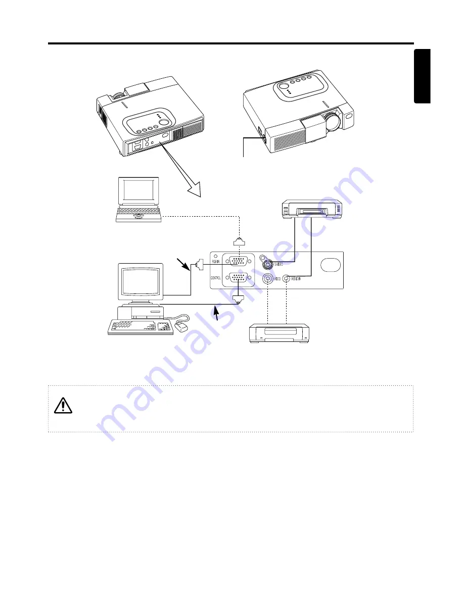
Example of system setup

AC Inlet

Video tape recorder with S jack

Video tape recorder

Computer

(desktop type)

Computer

(notebook type)

Plug & Play

This projector is VESA DDC 1/2B compatible. Plug & play is possible by connecting to a computer
that is VESA DDC (Display Data Channel) compatible.
(Plug & play is a system configured with peripheral equipment including a computer and display,
and an operating system.

NOTE

: Use the RGB cable included with this projector when using plug & play. With other cables,

pins (12) (14) (15) are sometimes not connected.

RGB Cable

RS-232C Cable

Connecting with notebook computer

When connecting with notebook computer, set to valid the RGB external image output
(setting CRT display or simultaneous display of LCD and CRT).
Please read instruction manual of the notebook for more information.

Summary of Contents for CP-S220W

Page 1: ...D ISTRUZIONI Vi preghiamo voler leggere attentamente il manuale d sitruzioni in modo tale da poter comprendere quanto riportato ai fini di un corretto utilizzo del proiettore MANUAL DE USUARIO Lea cuidadosamente este manual del usuario para poder utilizar corretamente el producto GEBRUIKSAANWIJZNG Lees voor het qebruik alstublieft deze handleiding aandachtig door om volledig profijt te hebben van ...

Page 2: ...P 20 Symptom P 21 SPECIFICATIONS P 22 WARRANTY AND AFTER SERVICE P 23 REGULATORY NOTICES P 24 Tables Table 1 Installation Reference P 5 Table 2 Basic Operations P 9 Table 3 Setup Menu P 11 Table 4 Input Menu P 12 Table 5 Image Menu P 13 Table 6 Options Menu P 14 Table 7 No Signal Menu P 15 Table 8 OSD Message P 19 Table 9 Indicator Message P 20 Table 10 Symptom P 21 Table 11 Specifications P 22 NO...

Page 3: ...er viewing Distortion correction function Distortion free images are quickly available BEFORE USE Contents of package Make sure all of the following items are included in the package If anything is missing please contact your dealer NOTE Keep the original packing material for future reshipment Projector User s Manual this manual Safety Instructions Power Cord US Type Power Cord UK Type Power Cord ...

Page 4: ...OJECTOR RESET Button MUTE Button INPUT Button STANDBY ON Button Foot Adjuster Button Air Filter and Intake for the Cooling Fan Speaker Rear Foot Adjuster LAMP Indicator TEMP Indicator POWER Indicator MENU Button Ventilation Openings exhaust REAR RIGHT VIEW OF THE PROJECTOR Terminal Panel Refer below S VIDEO Terminal RGB IN Terminal CONTROL Terminal VIDEO Terminal Remote Control Sensor AUDIO IN Ter...

Page 5: ...he transparent filmsome of which is inside the battery folder Pull out the protection film to load the battery Replacing 1 See the reverse side of the remote controller 2 Pinch the groove and pull out battery holder as the drawing right 3 Remove the worn battery 4 Install the new battery with side facing 5 Push in and click the battery holder Pull out side Battery Holder Refer to P 8 OPERATIONS CA...

Page 6: ...bottom of the projector to adjust the projection angle It is variable within 0 to 10 approximately 1 Lift up the front side of the projector and pressing the foot adjuster button adjust the projection angle 2 Release the button to lock at the angle to be fixed 3 Turn the rear foot adjuster to adjust the left right slope Do not release the foot adjuster button unless the projector is being held oth...

Page 7: ...the S VIDEO terminal of the projector and the optional cable for S Video Audio Signal Input Connect the AUDIO IN terminal of the projector to the audio signal output by the enclosed audio cable RS 232C Connect the CONTROL terminal of the projector to the computer by the optional RS 232C cable Refer to the manual of the RS 232C cable for the control command Cabling Incorrect connecting could result...

Page 8: ...y Data Channel compatible Plug play is a system configured with peripheral equipment including a computer and display and an operating system NOTE Use the RGB cable included with this projector when using plug play With other cables pins 12 14 15 are sometimes not connected RGB Cable RS 232C Cable Connecting with notebook computer When connecting with notebook computer set to valid the RGB externa...

Page 9: ...nd lamp cooling begins The Power indicator blinks orange during lamp cooling Pressing the STANDBY ON button has no effect while the Power indicator is blinking 2 The system assumes the Standby mode when cooling is complete and the Power indicator ceases blinking and changes to orange Check that the indicator is orange and set the Power switch to O 3 The Power indicator is extinguished when power i...

Page 10: ...con is displayed in the POSITION mode Image position adjustment Press the and buttons in the position adjustment mode Valid only in the MAGNIFY mode with VIDEO S VIDEO input The icon is extinguished and the position adjustment mode cleared automatically after approximately ten seconds of inactivity RESET Initialise menu items Select an item and press the RESET button Initialise position adjustment...

Page 11: ... start stop Press the TIMER button Count down and display by the minute from the initial value 1 99 set in TIMER on the Options menu to 0 The timer is not displayed in the BLANK MODE or FREEZE MODE BLANK ON OFF Set Clear Blank mode Press the BLANK button No image is displayed in the Blank mode The screen color is as set in BLANK on the Image menu MENU ON OFF Menu display start stop Press the MENU ...

Page 12: ...TUP INPUT OPT IMAGE Item Description RGB VIDEO S VIDEO BRIGHT Adjustment Dark Light CONTRAST Adjustment Weak Strong V POSIT Adjustment Down Up H POSIT Adjustment Left Right H PHASE Adjustment Left Right Adjust to eliminate flicker H SIZE Adjustment Small Large The image may not displayed correctly if the horizontal size is excessive In such cases press the RESET button and initialise the horizonta...

Page 13: ...ction when the image becomes unstable eg the image becomes irregular or lacks color Auto Adjust requires approximately ten seconds It may not function correctly with some input signals Pressing the AUTO button in this case may correct this problem AUTO Automatic adjustment at RGB input Select EXECUTE with the button Horizontal position vertical position clock phase and horizontal size are automati...

Page 14: ...ith the and buttons The image is cleared when the BLANK mode is set with BLANK ON or when there is no signal and the entire screen is displayed in the selected color Note that if TURN OFF is selected on the START UP the blank screen is displayed in blue when there is no signal MIRROR Operation start stop Press the or button Select Mirror status Select mirror status with and buttons START UP Operat...

Page 15: ...eration start stop Press the or button Select menu display language Select with the and buttons AUTO OFF Operation start stop Press the or button Set AUTO OFF Set 1 99 minutes with the and buttons The system automatically enters the standby mode when a signal is not received for the set time Clear AUTO OFF Select STOP 0 min with the button Wind Stop is selected the system does not enter the standb...

Page 16: ...tons START UP Operation start stop Press the or button Setup initial screen display Select TURN ON with the button Clear initial screen display Select TURN OFF with the button Note that if TURN OFF is selected the blank screen is displayed in blue when there is no signal MENU COLOR Select menu background color Select with the and buttons TIMER Operation start stop Press the or button Setup initial...

Page 17: ...MAINTENANCE Lamp HIGH VOLTAGE HIGH TEMPERATURE HIGH PRESSURE Contact your dealer before replacing the lamp Option lamp DT00301 Before replacing the lamp switch power OFF remove the power cord from the power outlet and wait approximately 45 minutes until the lamp has cooled The lamp may explode if handled at high temperatures Lamp Life Projector lamps have a finite life The image will become darker...

Page 18: ...sult in injury or accidents Do not use the projector with the lamp cover removed Resetting the Lamp Timer Reset the lamp timer after replacing the lamp When the lamp has been replaced after the LAMP indicator is red or the CHANGE THE LAMP message is displayed complete the following operation within ten minutes of switching power ON The power will be turned off automatically in over 10 minutes 1 Sw...

Page 19: ...tergent and wipe dry with a soft dry cloth Switch power OFF and remove the power cord from the power outlet before beginning maintenance work Please read the separate SAFETY INSTRUCTIONS thoroughly to ensure that maintenance is performed correctly Replace the air filter if contamination cannot be removed or if it is damaged Contact your dealer in such case Option Air filter MU01291 Do not use the ...

Page 20: ...reset the lamp timer after replacing the lamp CHANGE THE LAMP AFTER REPLACING LAMP RESET THE LAMP TIME THE POWER WILL TURN OFF AFTER 0 hr The lamp has reached the end of its life Power will be switched OFF in a few moments Switch power OFF immediately and replace the lamp as shown in P 16 Lamp Always reset the lamp timer after replacing the lamp NO INPUT IS DETECTED ON No input signal found Check ...

Page 21: ...tted in correctly Switch power OFF and wait for 45 minutes until the equipment cools Check fitting of the lamp and lamp cover and switch power ON again Contact your dealer if the same problem occurs again Lights red Turns off Blinks red The cooling fan is not operating Switch power OFF and wait for 20 minutes until the equipment cools Check for foreign matters in the fan and switch power ON again ...

Page 22: ...correctly 6 7 Video is present but no audio The projector is not correctly connected Connect correctly 6 7 The volume is seet to minimum Press VOLUME on the remote control or display the menu screen and adjust the volume 10 14 Mute is turned on Press the MUTE button 10 Audio is present but no video The projector is not correctly connected Connect correctly 6 7 The brightness adjustment knob is rot...

Page 23: ... x 210 D mm Weight mass 2 4 kg or less INPUT signal RGB Video Analog 0 7Vp p 75Ω terminator positive H V sync TTL level positive negative Compound sync TTL level D sub 15 pin shrink jack 5 1 10 6 15 11 7 Ground Green 8 Ground Blue 9 1 Video input Red 10 Ground 2 Video input Green 11 3 Video input Blue 12 DDC jack 4 13 H sync Compound sync 5 Ground DDC 14 Vertical sync 6 Ground Red 15 DDC jack VIDE...

Page 24: ... with the equipment first refer to the P 19 TROUBLESHOOTING section and run through the suggested checks If this does not resolve the problem contact your dealer or service company If repairs are possible and desirable they will be charged Unit mm This product is supplied with a written warranty Please read it thoroughly enter the required details and storage in a safe place ...

Page 25: ...rrect the interference by one or more of the following measures Reorient or relocate the receiving antenna Increase the separation between the equipment and receiver Connect the equipment into an outlet on a circuit different from that to which the receiver is connected Consult the dealer or an experienced radio TV technician for help INSTRUCTIONS TO USERS This equipment complies with the requirem...

Page 26: ... ITALY Tel 39 02 487861 Tel 39 02 38073415 Servizio Clienti Fax 39 02 48786381 2 Email customerservice italy hitachi eu com HITACHI Europe AB Box 77 S 164 94 Kista SWEDEN Tel 46 0 8 562 711 00 Fax 46 0 8 562 711 13 Email csgswe hitachi eu com HITACHI EUROPE S A S Lyon Office B P 45 69671 BRON CEDEX FRANCE Tel 04 72 14 29 70 Fax 04 72 14 29 99 Email france consommateur hitachi eu com HITACHI EUROPE...

Reviews: