background image

Appuyez sur la touche RECALL du boîtier de
télécommande pour afficher sur l’écran l’état
des signaux d’entrée.

Appuyez une nouvelle fois sur la touche
RECALL pour abandonner l’affichage sur
l’écran.

• L'affichage sur l'écran après 5 secondes.

FRANÇAIS

11

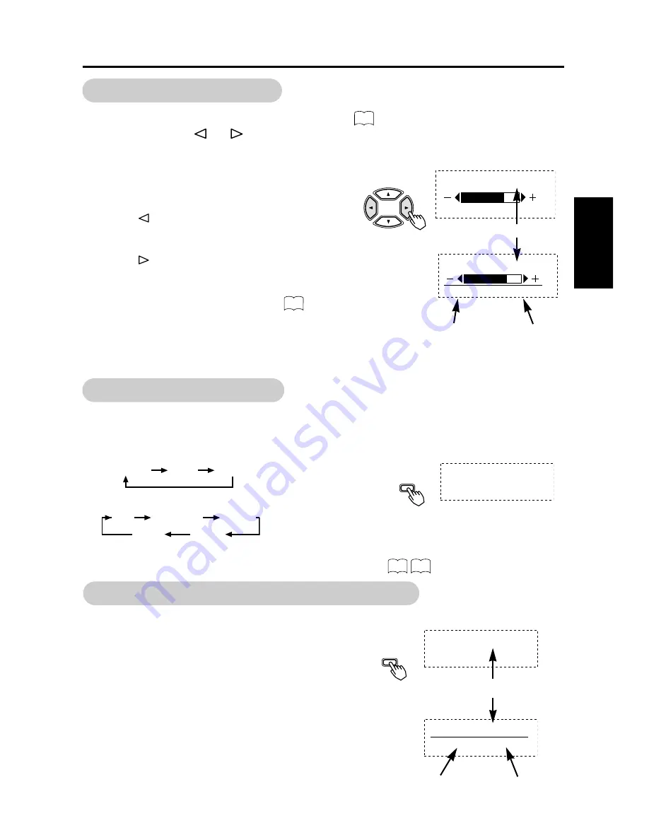
Tandis que le système d’affichage sur l’écran       , n’est pas visible, appuyez sur la
touche SELECT 

ou 

du boîtier de télécommande pour régler le contraste.

• Quand vous appuyez sur ces touches, le réglage du

contraste et les fréquences horizontal (H) et
verticale (V) du signal d’entrée sont affichées à
titre d’aide.(Pour une entrée RVB seulement)

• Tandis que l’aide est affichée, appuyez sur la

touche 

pour réduire la différence entre la partie

la plus sombre et la partie la plus lumineuse.

• Tandis que l’aide est affichée, appuyez sur la

touche 

pour accroître la différence entre la

partie la plus sombre et la partie la plus lumineuse.

• Vous pouvez également régler le contraste grâce

au système d’affichage sur l’écran.

• Le mode permettant le réglage du contraste est

abandonné si vous n’appuyez sur aucune touche
pendant 5 secondes. (L’aide au réglage s’efface
d’elle-même.)

Boîtier de

télécommande

CONTRASTE : 100

H :

**

.


*

kHz, V :

**

.


*

Hz

Réglage du contraste

Fréquence d’entrée
horizontal

Fréquence d’entrée
verticale

Aide au réglage

Réglage du contraste

12

13

Boîtier de

télécommande

RECALL

Affichage de l’état du signal d’entrée

 RVB1  [D-SUB]

 H : 46.5kHz, V : 60.0Hz

Nom de la prise d’entrée

Fréquence d’entrée
horizontale

Fréquence d’entrée
verticale

VIDÉO

RVB

 CONTRASTE : 100

 VIDÉO2  [COMPONENT]

VIDÉO

RVB

Chaque pression sur le bouton SIZE de la télécommande change la taille
d’affichage de l’écran (ou la zone d’affichage) dans l’ordre suivant.Le mode
sélectionné est affiché sur la partie inférieure de l’écran.

•Signal d’entrée RVB

•Signal d’entrée VIDÉO

• Selon le type de signal, il peut arriver qu'il ne soit pas possible de modifier la taille de

l'écran. Certaines tailles peuvent ne pas être disponibles.

Sélectionner la taille

SIZE

Boîtier de

télécommande

TOTAL

 NORMAL        TOTAL       ZOOM

4:3       PANORAM       FILM1

TOTAL           FILM2

15

16

Summary of Contents for CMP4121HDU

Page 1: ...n the rear of the monitor This monitor is ENERGY STAR compliant when used with a computer equipped with VESA DPMS The ENERGY STAR emblem does not represent EPA endorsement of any product or service As an ENERGY STAR Partner Hitachi Ltd has determined that this product meets the ENERGY STAR guidelines for energy efficiency Color Plasma Display Monitor Model The stand is an option Le socle est en op...

Page 2: ... MARQUES DÉPOSÉES VGA et XGA sont des marques déposées d International Business Machines Corporation APPEL et Macintosh sont des marques déposées d Apple Computer Inc VESA est une marque déposée d une organisation sans but lucratif La Video Electronics Standard Association Toutes les marques ou noms de produit sont des marques de commerce ou des marques déposées de leur dépositaire respectif NOTA ...

Page 3: ...njury or damage of your properties WARNING CAUTION Fire or electric shock may cause death or serious injury unless you follow the instruction below WARNING If something smells strange or smoke comes from the monitor Turn off the monitor and disconnect the power plug from the mains immediately Contact service center after confirming that the smoking has stopped If you continue to operate the monito...

Page 4: ...d is damaged call service center Fire or electric shock may cause death or serious injury unless you follow the instruction WARNING The enclosed power cord must be used Failure to do so may cause electric shock hazard or fire hazard In USA Canada use a UL LISTED CSA LABELLED or CERTIFIED power cord set meeting the following specifications Rating min 125V 10A Length max 3 0m Type SVT or SJT Plug ty...

Page 5: ... advised to move the monitor with two persons Handle with care when you move the monitor particularly take care of glass screen When you disconnect the power plug You have to grasp the power plug itself do not pull the power cord If you pull the power cord you may damage it and it may cause a fire or an electric shock Do not touch the power plug just after disconnecting it from the mains or you ma...

Page 6: ...or complete isolation For complete isolation from the mains remove the power cord from the monitor or from the wall socket Protection against Minimum number of fuses or circuit breaker poles Location Case A Equipment to be connected to POWER SYSTEMS with earthed neutral reliably identified except for Case C below Earth faults 1 Phase conductor Overcurrent 1 Either of the two conductors Case B Equi...

Page 7: ...om time to time Please watch the monitor in downward direction Note on image retention The plasma monitor illuminates phosphor to display images The phosphor has a finite illumination life After extended periods of illumination the brightness of the phosphor would be degraded to such extent that still images would image retention that part of the screen as grayed out images Tips to prevent such im...

Page 8: ...above Precautions for the monitor Use the attached signal cable when you connect the monitor with PC equipment Do not use other signal cables Confirm the connector is fixed tightly when the signal cable is connected Also confirm the screws on the connector are tightened Plug the power cord of the monitor into a different socket from that for other equipment such as Radio etc Use a plug with ground...

Page 9: ...tions provided that following conditions are met Video inputs The input signal amplitude must not exceed the specified level CAUTION Changes or modifications not expressly approved by the party responsible for compliance could void the user s authority to operate the equipment Declaration of Conformity According to 47CFR Part 2 and 15 for Class B Personal Computers and Peripherals and or CPU Board...

Page 10: ...iteur Si vous notez que le moniteur émet une odeur inhabituelle Si de l eau a pénétré dans le moniteur Si vous avez laissé tomber le moniteur ou si le coffret est endommagé 1 Mettez hors tension le moniteur 2 Débranchez la fiche du cordon d alimentation au niveau de la prise secteur 3 Faites réparer l appareil AVERTISSEMENT ATTENTION Des avertissements et des précautions figurent dans ce document ...

Page 11: ...isez pas le moniteur si la vitre est cassée ou endommagée Si après avoir heurté le moniteur vous constatez que l image ne se forme plus sur l écran que le verre est brisé que le moniteur émet de la fumée ou une odeur inhabituelle mettez immédiatement le moniteur hors tension et débranchez la fiche du cordon d alimentation au niveau de la prise secteur Cela fait faites réparer le moniteur Si vous v...

Page 12: ...tomatiquement sur la tension d entrée 100 120 200 240 V FAITES ATTENTION AU BRANCHEMENT DU CORDON D ALIMENTATION Avant de brancher la prise mâle du cordon d alimentation sur une prise murale de tension correcte vérifiez que la partie de ce cordon qui se trouve au niveau de la connexion est propre c est à dire qu il n y a pas de poussière Ensuite enfoncez fermement la prise mâle de ce cordon dans u...

Page 13: ...igine d un incendie ou d une secousse électrique Par ailleurs ne touchez pas les broches de la fiche du cordon d alimentation immédiatement après avoir débranché cette fiche au niveau de la prise secteur car vous pourriez ressentir une secousse électrique Débranchez la fiche du cordon d alimentation au niveau de la prise secteur si vous envisagez de ne pas vous servir du moniteur pendant une longu...

Page 14: ...nt à des SCHÉMAS D ALIMENTATION avec neutre à la terre identifié de façon sûre excepté pour le cas C ci dessous Défaut à la terre 1 Conducteur de phase Surintensité 1 L un ou l autre des conducteurs Cas B Matériel destiné à être relié à toute alimentation y compris les SCHÉMAS D ALIMENTATION IT et les alimentations avec fiches réversibles excepté pour le cas C ci dessous Défaut à la terre 2 Deux c...

Page 15: ...Reposez vos yeux en regardant de temps en temps autre chose que le moniteur Veillez à ce que vos yeux soient plus hauts que le moniteur Remarque sur les images rémanentes L écran à plasma éclaire des éléments de phosphore pour afficher les images Le phosphore a une durée de vie finie Après une longue période l éclairage la luminosité d un élément de phosphore peut se dégrader et entraîner des brûl...

Page 16: ...adio quand vous utilisez le moniteur reportez vous à ce qui précède Précautions concernant le moniteur Pour relier le moniteur à un PC utilisez le câble de signal fourni N utilisez aucun autre câble de signal Assurez vous que le connecteur du câble de signal est bien fixé Veillez à ce que les vis soient serrées Branchez la fiche du cordon d alimentation sur une prise secteur différente de celle ut...

Page 17: ...duct names mentioned in this manual may be trademarks or registered trademarks of their respective owners SAFETY GUIDELINES I CONTENTS 1 FEATURES 2 STANDARD ACCESSORIES 2 INSTALLATION INSTRUCTIONS 3 Installation 3 Anti tumble measures 3 Component Names 4 Installation and Cabling 6 Handling the Remote Controller 8 OPERATING INSTRUCTIONS 9 Turning Power On and Off 9 Input Selection 10 Volume Adjustm...

Page 18: ... panel with a resolution of 1024 H x 1024 V pixels creates a high definition large screen aspect ratio 16 9 and low profile flat display Free from electromagnetic interferences from geomagnetic sources and ambient power lines the panel produces high quality display images free from color misconvergence and display distortion Multimedia input support The monitor is provided with a mini D Sub connec...

Page 19: ...d clamp secure the set to a firm wall or pillar Securing desktop 1 Using wood screws two fasten the set to the clamping screw holes on the rear of the stand as shown 2 Using commercially available wood screws secure the set firmly in position Using the optional vertical mount unit CMPAK14 Using the optional wall mount unit CMPAK14 allows set to mount on wall surfaces as shown at right 1 Make at le...

Page 20: ...panel VOLUME button MENU button INPUT SELECT button SELECT button Adjustment buttons are located on the bottom The inner side of the cover is provided with indications to distinguish the adjustment buttons SUB POWER button Component Names 9 10 12 12 10 9 9 The main power switch is located at the back on the lower surface The stand is an Optional ...

Page 21: ...IDEO 2 VIDEO 1 SIZE button POWER ON OFF button MUTE button MENU button VOLUME button SELECT button 9 10 12 10 12 11 External speaker terminals 7 RECALL button 11 RGB VIDEO button 10 POWER OFF button 9 POWER ON button 9 Handgrips Caution when moving the main unit As this product is heavy whenever it is moved two people are required to transport it safely Whenever the unit is moved it should be lift...

Page 22: ...not match your PC consult your dealer after reading the section Signal Input 5 Insert one end of the power cable included into the rear panel power cable connector and the other end into a power socket 6 Turn on the monitor then the PC to make sure that a display image appears on the monitor screen For instructions on turning on the monitor and adjusting its display images see Operating Instructio...

Page 23: ...minals To component output terminals To component input terminals To audio video input terminals To audio input terminals Video equipment such as a video disc player a DVD player and a video camera Monitor rear panel External Monitor Power cable Power cable connector Red R AUDIO IN R L MONO AUDIO IN COMPONENT COMPOSITE S VIDEO 2 VIDEO 1 R PR CR PB CB Y IN IN OUT L MONO Speaker R Speaker L White L ...

Page 24: ...o not use new and old batteries together The batteries could explode or leak resulting in fires physical injury or stains When loading batteries observe their correct polarities as marked on the product If loaded in the wrong direction the batteries could explode or leak resulting in fires physical injury or stains TIPS Do not drop or impact the remote controller Do not splash the remote controlle...

Page 25: ... the front of the frame is ON 23 TIPS Avoid repeatedly turning the monitor on and off at short time intervals Failures might result from such operation Turn off the main power switch before leaving the monitor out of use for an extended period of time If a power failure occurs while the main unit is running it would be powered on upon recovery from the failure Turn off the unit main power switch b...

Page 26: ... disappear automatically VOLUME VOLUME VOLUME VOLUME ENGLISH 10 OPERATING INSTRUCTIONS continued Main unit Remote controller VOLUME VOLUME VOLUME RGB1 D sub input When using INPUT SELECT RGB2 BNC input VIDEO1 composite or S input VIDEO2 COMPONENT input Input Selection Remote controller Main unit RGB 2 RGB 1 VIDEO 2 VIDEO 1 INPUT SELECT Volume Adjustment 12 14 VOLUME 30 Sound volume setting Adjustm...

Page 27: ...tical V frequencies of the input signal will be displayed in a guidance image For RGB input only While the guidance is on display press the key to narrow the difference between darkness and brightness While the guidance is on display press the key to widen the difference between darkness and brightness You can also adjust the contrast setting via the on screen display system The contrast adjustmen...

Page 28: ...and VOLUME button to exit to the original menu For information on adjusting and setting choices see to Press the MENU button once again to exit the MAIN MENU The MAIN MENU will close automatically when no keys are entered for 10 seconds ENGLISH 12 OPERATING INSTRUCTIONS continued MAIN MENU PICTURE SOUND DISPLAY FUNCTION Remote controller MENU PICTURE MENU CONTRAST 127 BRIGHTNESS 0 COLOR 0 TINT 0 S...

Page 29: ...mum visibility to suit the ambient brightness BRIGHTNESS Black is subdued for increasedoverall darkness Black is set off for increased overall brightness Adjust to prevent black from spreading across the screen COLOR Lightens colors Darkens colors Adjust for desired density somewhat for lighter colors for a natural look TINT Enhances red and weakens green Enhances green and weakens red Adjust for ...

Page 30: ...set to 10 or 20 NORMAL 20 10 RGB Normally set to 0 7 V If white is found to spread across the screen set to 1 0 V Set to 0 7 V Set to 1 0 V VIDEO ENHANCE Set to OFF Set to ON ON enhances vertical lines Normally set to ON R GAIN Red is weakened Red is strengthened Sets the color adjustment selected by the user with COLOR SELECT USER mode takes effect automatically when an attempt is made to set a g...

Page 31: ...nput DISPLAY INIT INITIALIZE Clear the user signal preset data Set to YES Clears all DISPLAY MENU adjustment values exept DISPLAY AREAand exits to the DISPLAY MENU Set to NO Exits to the DISPLAY MENU without clearing the menu adjustment values RGB DISPLAY MENU DISPLAY AREA NORMAL AUTO ADJUST MANUAL ADJUST INTERPOLATION LINEAR WIDE MODE OFF DISPLAY INIT RETURN NORMAL MAIN MENU PICTURE SOUND DISPLAY...

Page 32: ... phase shifts slightly to right Adjust for clear character visibility MAIN MENU PICTURE SOUND DISPLAY FUNCTION DISPLAY MENU DISPLAY AREA NORMAL AUTO ADJUST MANUAL ADJUST INTERPOLATION LINEAR DISPLAY INIT RETURN RGB MANUAL ADJUST MENU H POSITION 0 V POSITION 0 CLOCK 0 PHASE 0 RETURN RGB DISPLAY MENU VIDEO MAIN MENU PICTURE SOUND DISPLAY FUNCTION DISPLAY MENU DISPLAY SIZE PANOR V POSITION 0 V SIZE 0...

Page 33: ...ng 4 3 MOVIE1 and FULL For component HD3 1035i 1080i 720p signals the display mode is not selectable If an S1 or S2 image is input from the S image of video1 the S1 image would be set to FULL and the S2 image would be set to MOVIE1 Displays by Selecting the DISPLAY SIZE VIDEO input When you want to Set the display size to Input signal Display screen Remarks Play a 4 3 image in a 16 9 screen faithf...

Page 34: ...g MODE RGB input only PC MOVIE The mode function added to the Function Menu allows for a smooth playback of movies from 60 Hz XGA input when it is set to MOVIE Normally keep the function menu set to PC OFF mode Set it to MOVIE ON when playing movies LINE INTP Set to OFF Set to ON Set to ON when playing a 3D video disc Set to OFF in most cases 3D COMB Set to OFF Set to ON Set to OFF if video images...

Page 35: ...T HD3 Pb Pr RETURN Cb Cr Pb Pr VIDEO FUNCTION MENU LANGUAGE ENG AUTO FREQ ON LINE INTP OFF 3D COMB ON COMPONENT VIDEO SYSTEM AREA1 SCREEN SAVER RETURN VIDEO Selected characters Setup hint ORBITER Set to OFF Set to ON Set to ON when high image retention potential exists such as static or still image displayed long period of time MOVING DOTS 1 3 2 Adjust as desired Reduces the amount of movement Inc...

Page 36: ...isplay Line correction Three dimensional Y C separation HD signal Language selection VOLUME BALANCE TREBLE BASS MUTE LEVEL AUTO FREQ LINE INTP 3D COMB COMPONENT LANGUAGE One set can be recorded During normal signal reception Contrast Brightness Color temperature Gamma correction Input signal level CONTRAST BRIGHTNESS COLOR SELECT GAMMA VIDEO LEVEL One set can be recorded during common RGB1 RGB2 in...

Page 37: ...Vertical size V SIZE VIDEO1 VIDEO2 Changes in the signal status are displayed on the screen as they arise RGB1 D SUB H 46 5kHz V 60 0Hz POWER SAVE OUT OF FREQUENCY Either VIDEO or S VIDEO is displayed on VIDEO input Signal Check Status Display Action The input signal was switched or the RECALL button was pressed after AUTO FREQ was turned on The input terminal and the horizontal and vertical frequ...

Page 38: ...m operates to reduce the power consumed by the sunit Video signal Yes No Screen display Active normal display Blank no video Operation mode On Off Indicating lamp Lights green Blinks green Power consumption 360W Sound off 5W or less Sound Mode If you press the MENU button while the monitor has power save mode turned off sound output is enabled by cancelling the off setting of power save mode When ...

Page 39: ...Y An input signal is not received normally Check to see if the input signal matches the monitor specifications Check the way the signal cable is connected The power indicating lamp is normally lit but no picture Check the contrast and brightness settings adjust them for higher contrast and brightness Check the way the signal cable is connected The display image appears flowing slantwise Text displ...

Page 40: ...ntents in rare cases this may cause vertical stripes to appear because of failure to light Please note that this is not a malfunction Coarse horizontal stripes appear in FULL display Adjusting the phase will reduce the horizontal stripes RGB input The display dims to make the picture invisible during special playback of a VCR FF REW This condition may occur when the unit is connected to a VCR with...

Page 41: ...C ABC ABC Adjustment procedure 1 Press MENU button to open the MAIN MENU 2 Press SELECT button several times to choose DISPLAY 3 Press to open the DISPLAY MENU 4 Press to choose AUTO ADJUST 5 Press ADJUST OK Adjust the by displaying a fine pattern such as a character string or vertical streak pattern across the screen If AUTO ADJUST does not work well 6 Press MENU button to open the MAIN MENU 7 Pr...

Page 42: ... ADJUST OK Adjust the by displaying a fine pattern such as a character string or vertical streak pattern across the screen If AUTO ADJUST does not work well 6 Press MENU button to open the MAIN MENU 7 Press SELECT button several times to choose DISPLAY 8 Press to open the DISPLAY MENU 9 Press to choose MANUAL ADJUST 10 Press to open the MANUAL ADJUST MENU 11 Press several times to choose PHASE Adj...

Page 43: ... analog RGB horizontal 24kHz to 107kHz vertical 50Hz to 85Hz 1080 50i 1080 60i NTSC NTSC 4 43 M PAL PAL N PAL SECAM 480 60i 480 60p 720 60p 1080 60i 1035 60i 575 50i Sync signals H V separate TTL level 2KΩ H V composite TTL level 2KΩ Sync on green 0 3 Vp p 75Ω Video output Signal Through output BNC for VIDEO1 input signals Recommended Signal 27 modes 10 modes Audio output terminal 8W 8W 8Ω Input p...

Page 44: ...ignals in the following priority order Sync signal type Priority H V separate sync 1 H V composite sync 2 sync on Green 3 RGB terminal BNC connector V sync H sync or H V composite sync G video or sync on green R video B video S input connector pin specifications Serial connector pin specifications Pin Input signal Remarks 1 No connection 2 RXD Unit PC 3 TXD Unit PC 4 No connection 5 GND Unit GND P...

Page 45: ...2 19 48 08 50 00 9 800 X 600 75 00 46 88 49 50 10 800 X 600 85 06 53 67 56 25 11 1024 X 768 60 00 48 36 65 00 12 1024 X 768 70 07 56 48 75 00 13 1024 X 768 75 03 60 02 78 75 14 1024 X 768 85 00 68 68 94 50 15 1152 X 864 75 00 67 50 108 00 16 1280 X 1024 60 02 63 98 108 00 17 1280 X 1024 75 03 79 98 135 00 18 1280 X 1024 85 02 91 15 157 50 19 1600 X 1200 60 00 75 00 162 00 20 1600 X 1200 75 00 93 7...

Page 46: ...not be reproduced correctly with an extremely long front porch or back porch or with an extremely short data display time Front porch Sync width Back porch Blanking width Horizontal timing Horizontal frequency 24 kHz to 52 kHz 0 2 µs or more 1 0 4 0 µs 1 2 µs or more 3 5 µs or more Horizontal frequency 52 kHz to 106 kHz 0 2 µs or more 0 8 3 0 µs 1 1 µs or more 2 3 µs or more Vertical timing 9 µs o...

Page 47: ... être des marques déposées ou non par leurs propriétaires respectifs INSTRUCTIONS DE SÈCURITÈ VIII CONTENTS 1 PARTICULARITÈS 2 ACCESSOIRES STANDARD 2 INSTRUCTIONS D INSTALLATION 3 Instruction 3 Pour éviter la chute 3 Nom des parties 4 Installation et câblage 6 Utilisation du boîtier de télécommande 8 INSTRUCTIONS DE FONCTIONNEMENT 9 Mise sous tension et hors tension 9 Sélection de l entrée 10 Régl...

Page 48: ...n support plat A l abri des influences électromagnétiques produites par les sources géomagnétiques et les lignes sous tension cet écran fournit des images à très haute définition totalement dépourvues d erreur de convergence de couleur ou de distorsion Entrée multimédia Le moniteur est fourni avec un connecteur mini D Sub et un connecteur BNC pour entrée RGB un connecteur Composite S vidéo et un c...

Page 49: ... utilisation du module de montage mural optionnel CMPAK14 permet de monter le moniteur sur une surface murale de la façon montrée ci à droite 1 Préparez au moins quatre jeux de boulon d ancrage et de vis afin à pouvoir réaliser l installation avec divers types de mur 2 Lisez attentivement les instructions fournies avec le module de montage mural pour placer de façon optimale l écran à plasma sur l...

Page 50: ... bouton de réglage se trouve sur le fond Le côté intérieur du couvercle contient des indications permettant de distinguer les boutons de réglage Touche Alimentation secondaire Nom des parties 9 10 12 12 10 Interrupteur d alimentation principal Témoin 9 9 L interrupteur d alimentation secteur se trouve au dos sur la surface inférieure Le socle est un accessoire supplémentaire en option ...

Page 51: ... 1 RGB 2 D SUB IN RS232C Prises de raccordement d enceintes extérieures 7 7 6 Boîtier de télécommande SIZE RGB 2 VOLUME VOLUME MUTE MENU RECALL RGB 1 VIDEO 2 VIDEO 1 9 10 12 10 12 11 Prises de raccordement d enceintes extérieures 7 11 10 9 9 Poignées Précaution au déplacement de l unité principale Comme ce produit est pesant deux personnes sont requises pour le déplacer sans danger Lors d un dépla...

Page 52: ...r après avoir lu les conseils du paragraphe Entrée du signal 5 Branchez l une des extrémités du cordon d alimentation fourni dans le connecteur de cordon d alimentation du panneau arrière et l autre extrémité dans une prise secteur 6 Mettez le moniteur sous tension puis le PC et assurez vous qu une image se forme sur le moniteur Pour de plus amples détails concernant la mise sous tension du monite...

Page 53: ...ortie audio et vidéo Vers les prises d entrée des composantes Vers les prises de sortie des composantes Vers la prise de sortie S vidéo Vers la prise d entrée S vidéo Vers les prises d entrée du signal audio Appareil vidéo tel qu un lecteur de LaserDISC un lecteur de DVD DSS ou un caméscope Panneau arrière du moniteur Vers la prise de sortie du signal Cordon d alimentation Fiche du cordon d alimen...

Page 54: ...er de télécommande N utilisez pas en même temps une pile neuve et une pile usagée Les piles pourraient exploser ou fuir ce qui pourrait provoquer un incendie une blessure ou des taches Lors de la mise en place des piles veillez à respecter les polarités indiquées sur l appareil Dans le cas contraire les piles pourraient exploser ou fuir ce qui pourrait provoquer un incendie une blessure ou des tac...

Page 55: ...e télécommande SUB POWER Mise sous tension et hors tension Témoin Etat d alimentation Fonctionnemment Eteint Eteint Lorsque l interrupteur d alimentation principal est réglé sur OFF S allume en rouge Eteint veille Lorsque le commutateur principal est sur ON et que le touche de la télécommande ou le touche SUB POWER situé sur le dessous de l avant du cadre est sur OFF S allume ou clignote en vert A...

Page 56: ...reréglez la PHASE du signal utilisé FRANÇAIS 10 INSTRUCTIONS DE FONCTIONNEMMENT suite Appareil Boîtier de télécommande VOLUME VOLUME VOLUME RVB1 Entrée D sub Si vous utilisez INPUT SELECT RVB2 Entrée BNC VIDEO1 Entrée composite ou S VIDEO2 Entrée COMPOSANT Sélection de l entrée Boîtier de télécommande Appareil RGB 2 RGB 1 VIDEO 2 VIDEO 1 INPUT SELECT Réglage du niveau sonore 12 14 VOLUME 30 Réglag...

Page 57: ...e grâce au système d affichage sur l écran Le mode permettant le réglage du contraste est abandonné si vous n appuyez sur aucune touche pendant 5 secondes L aide au réglage s efface d elle même Boîtier de télécommande CONTRASTE 100 H kHz V Hz Réglage du contraste Fréquence d entrée horizontal Fréquence d entrée verticale Aide au réglage Réglage du contraste 12 13 Boîtier de télécommande RECALL Aff...

Page 58: ...t la touche VOLUME pour abandonner le menu initial Pour de plus amples détails concernant les réglages et les choix reportez vous aux pages à Appuyez une nouvelle fois sur la touche MENU pour abandonner le MENU PRINCIPAL Le menu de réglage se ferme de lui même si vous n appuyez sur aucune touche pendant 10 secondes INSTRUCTIONS DE FONCTIONNEMMENT suite MENU PRINCIPAL IMAGE SON AFFICHAGE FUNCTION B...

Page 59: ...LUMINOSITE Le noir est accru pour augmenter l obscurité générale Le noir est atténué pour diminuer l obscurité générale Réglez pour que la visibilité convienne à l obscurité l cut des cheveux noirs COULEURS Eclaircit les couleurs Assombrit les couleurs Réglez pour la densité requise plutôt vers les couleurs claires qui donnent un aspect naturel TEINTE Rehausse le rouge et affaiblit le vert Rehauss...

Page 60: ... ou 20 NORMAL 20 10 RVB Normalement réglé sur 0 7V Si le blanc envahit l écran réglez sur 1 0V Réglé sur 0 7V Réglé sur 1 0V NIVEAU VIDÉO Réglé sur OFF Réglé sur ON Réglez sur ON pour améliorer l affichage des lignes verticales Réglez normalement sur ON GAIN R Le rouge est affaibli Le rouge est renforcé Définit le réglage de couleur sélectionné par l utilisateur avec REG TEINTE Le mode UTILISAT se...

Page 61: ...nnées de signal définies par l utilisateur Réglez sur OUI Annule tous les ajustements du menu MENU ECRAN à l exception de ZONE ECRAN puis quitte le menu DISPLAY ECRAN Réglé sur NON Le menu d affichage réapparaît Les valeurs de réglage ne sont pas effacées RVB MENU ECRAN ZONE ECRAN NORMAL AUTO AJUSTE MANUEL AJUSTE INTERPOLATION LINEAR MODE LARGE OFF INIT ECRAN RETOUR NORMAL MENU PRINCIPAL IMAGE SON...

Page 62: ...èrement vers la droite Réglez pour obtenir les caractères les plus clairs possible MENU PRINCIPAL IMAGE SON AFFICHAGE FUNCTION MENU ECRAN ZONE ECRAN NORMAL AUTO AJUSTE MANUEL AJUSTE INTERPOLAT LINEAR INIT ECRAN RETOUR RVB MANUAL ADJUSTMENT MENU POSITION H 0 POSITION V 0 HORLOGE 0 PHASE 0 RETOUR RVB INSTRUCTIONS DE FONCTIONNEMMENT suite MENU ECRAN VIDÉO MENU PRINCIPAL IMAGE SON AFFICHAGE FUNCTION M...

Page 63: ...une suppression des deux côtés Reproduit une image 4 3 sur un écran 16 9 avec la hauteur et la largeur au milieu de l écran agrandie de la même façon et avec les deux côtés apparaissant agrandis PANOR Panoramique L image de taille 16 9 VISTA de l image 4 3 est reproduite exactement sur un écran 16 9 FILM1 L image 4 3 est dite boîte aux lettres letter box Dans certains cas il peut rester une suppre...

Page 64: ...de ajoutée au menu de fonction permet de reproduire en douceur les images d une entrée 60 Hz XGA quand elle est réglée sur FILM Normalement laissez le menu de fonction réglé sur PC hors service Réglez le sur FILM en service lors de la reproduction de films INTERPOLAT Réglé sur OFF Réglé sur ON Réglez sur ON pour la lecture d un disque vidéo 3D Réglez sur OFF dans la plupart des cas 3D COMB Réglé s...

Page 65: ... SDTV COMPOSANT HD1 480p COMPOSANT HD2 720p La valeur par défaut et Y Pb Pr COMPOSANT HD3 1080i Caractères choisis Conseil de réglage ORBITER Mise hors service OFF Mise en service ON Placez à ON quand le potentiel élevé de conservationd image existe comme la charge statique ou toujours longue périodeaffichée par image MOUOIR POINT Réduction de la quantité de mouvement Augmentation de la quantité d...

Page 66: ...aration Y C tridimensionnelle Signal ID Sélection de langue VOLUME BALANCE AIGUE BASSES NIVEAU ATTENUATION AUTO FREQ INTERPOLAT 3D COMB COMPOSANT LANGUE Il est possible d enregistrer un jeu Pendant la réception d un signal normal Contraste Luminosité Température de couleur Correction gamma Niveau du signal d entrée CONTRASTE LUMINOSITE REG TEINTE GAMMA NIVEAU VIDEO Il est possible d enregistrer un...

Page 67: ...difications du signal apparaissent sur l écran au fur et à mesure qu elles se produisent VIDÉO1 ECONOMIE D ENERGIE HORS FREQUENCE Soit VIDEO soit S VIDEO est affichée pour l entrée VIDEO Vérification du signal Etat Affichage Action Le signal d entrée a été changé ou la touche RECALL a été pressée après que la founction AUTO FREQ a été mise en service La prise d entrée et les fréquences horizontale...

Page 68: ...n de réduire la consommation d énergie de l appareil Signal vidéo Oui Non Affichage de l écran Activé affichage normal Ecran vide pas d affichage Mode de fonctionnement Marche Arrêt Témoin S allume en vert Clignote en vert Consommation 360 W Son coupé 5 W ou moins Mode sonore Si vous appuyez sur le touche MENU alors que le mode d économie d énergie est hors service la sortie des sons est possible ...

Page 69: ...RS FREQUENCE Un signal d entrée n est pas reçu normalement Assurez vous que le signal d entrée correspond au caractéristiques du moniteur Vérifiez la manière dont le câble de signal est connecté Le témoin d alimentation est normalement éclairé mais l écran apparaît vierge Vérifiez les réglages de contraste et de luminosité augmentez le contraste et la luminosité Vérifiez la manière dont le câble d...

Page 70: ...rticales en raison d une défaillance d allumage Ceci est normal Des bandes horizontales grossières apparaissent pendant l affichage PLEIN Ajuster la phase réduira les bandes horizontales entée RVB L affichage s assombrit et rend l image invisible pendant la lecture spéciale sur un magnétoscope avance rapide rebobinage Cela peut se produire quand l appareil est connecté à un magnétoscope muni de so...

Page 71: ...ur ouvrir le menu MENU PRINCIPAL 2 Appuyez plusieurs fois sur la touche SELECT pour choisir AFFICHAGE 3 Appuyez sur pour ouvrir le menu MENU ECRAN 4 Appuyez sur pour choisir AUTO AJUSTE 5 Appuyez sur AJUSTMENT OK Ajustez en affichant un motif fin tel qu une suite de caractères ou une traînée verticale sur l écran Si AUTO ADJUST ne fonctionne pas de façon satisfaisante 6 Appuyez sur la touche MENU ...

Page 72: ...uyez sur AJUSTMENT OK Ajustez en affichant un motif fin tel qu une suite de caractères ou une traînée verticale sur l écran Si AUTO ADJUST ne fonctionne pas de façon satisfaisante 6 Appuyez sur la touche MENU pour ouvrir le menu MENU PRINCIPAL 7 Appuyez plusieurs fois sur la touche SELECT pour choisir AFFICHAGE 8 Appuyez sur pour ouvrir le menu MENU ECRAN 9 Appuyez sur pour choisir MANUEL AJUSTE 1...

Page 73: ...izontale 24kHz à 107kHz vertical 50Hz à 85Hz 1080 50i 1080 60i NTSC NTSC 4 43 M PAL PAL N PAL SECAM 480 60i 480 60p 720 60p 1080 60i 1035 60i 575 50i Signaux de synchronisation H V séparées Niveau TTL 2KΩ H V composite Niveau TTL 2KΩ Synchronisation sur le vert 0 3 Vc c 75Ω Signal de la producion Vidéo Sortie BNC pour signaux d entrée VIDEO1 Signaux conseillés 27 modes 10 modes Prise de sortie aud...

Page 74: ...e de priorité suivant Type de signal de synchronisation Priorité Synchronisation séparée H V 1 Synchronisation composite H V 2 Synchronisation sur le vert 3 Prise RGB connecteur BNC Synchronisation V Synchronisation H ou synchronisation composite H V G vidéo ou synchronisation sur le vert R vidéo B vidéo Bornage du connecteur d entrée S Bornage du connecteur série Broche Signal d entrée Remarques ...

Page 75: ...800 X 600 72 19 48 08 50 00 9 800 X 600 75 00 46 88 49 50 10 800 X 600 85 06 53 67 56 25 11 1024 X 768 60 00 48 36 65 00 12 1024 X 768 70 07 56 48 75 00 13 1024 X 768 75 03 60 02 78 75 14 1024 X 768 85 00 68 68 94 50 15 1152 X 864 75 00 67 50 108 00 16 1280 X 1024 60 02 63 98 108 00 17 1280 X 1024 75 03 79 98 135 00 18 1280 X 1024 85 02 91 15 157 50 19 1600 X 1200 60 00 75 00 162 00 20 1600 X 1200...

Page 76: ...s être restitué si le front avant ou l arc arrière sont extrêmement longs ou avec un temps d affichage des données extrêmement bref Arc avant Largeur de synchronisation Arc arrière Largeur d arrêt Séquence horizontale Fréquence horizontale 24 kHz à 52 kHz 0 2 µs ou supérieurer 1 0 4 0 µs 1 2 µs ou supérieurer 3 5 µs ou supérieurer Fréquence horizontale 52 kHz à 106 kHz 0 2 µs ou supérieurer 0 8 3 ...

Page 77: ...49641B Hitachi America Ltd Computer Division 2000 Sierra Point Parkway Brisbane CA 94005 1835 U S A Tel 1 800 HITACHI Fax 1 650 244 7525 Hitachi Australia Ltd 13 15 Lyonpark Road North Ryde N S W 2113 Tel 61 02 9888 4100 Fax 61 02 9888 4144 ...

Reviews: