background image

21

PMML0204 rev.0-05/2010

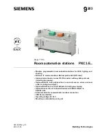
6.2  ELECTRICAL WIRING CONNECTION

The electrical wiring connection for the CH unit is shown in next figure.

1.    Turn OFF the main power switch and take off the electrical box cover of CH unit.
2.    Connect the power supply and earth wires to the terminals in the electrical box.
3.    Connect the wires of the operating line to the terminals in the electrical box.
4.    Tightly clamp the wires using the cord clamp inside the electrical box.
5.    Fix the electrical box cover after wiring work.

Terminal Board for Operating Line

CN

4

CN

3

CN

2

CN

1

PCN

1

PCB1

TB2

TB1

L1 L2

N

Terminal Board for Power Supply

Cord Clamp

Cord Clamp

Operating Line Connection

Earth Wire

Power Supply Line Connection


¡

Field minimum Wire Sizes

1.  Perform the electrical wiring work for the CH units. Determine the cable size according to the table below. 
2.  Pay attention to the marks on the terminal board when connecting wires for CH unit and I.U./O.U.  Refer to    
 

“Example of Electrical Wiring” for the wiring connection on the next page.

model

Power Source

maximum 

Current

Power Source Cable Size

Transmitting Cable Size

Earth

Wire Size

EN60 335-1 

mLFC 

EN60 335-1 

mLFC 

CH-6.0N1

1~ 220-240V/1Ø/50Hz

1A

0.75mm

2

0.5mm

2

0.75mm

2

0.5mm

2

2.0mm

2

CH-10.0N1

NOTE:


-

Follow local codes and regulations when selecting field wires.


-

The wire sizes marked with 

 in the above table are selected at the maximum current of the unit according to the European 

Standard, EN60 335-1.  Use the wires which are not lighter than the ordinary tough rubber sheathed flexible cord (code 

designation H05RN-F) or ordinary polychloroprene sheathed flexible cord (code designation H05RN-F).


-

The wire sizes marked with 

 in the above table are selected at the maximum current of the unit according to the wire, MLFC 

(Flame Retardant Polyflex Wire) manufactured by Hitachi Cable Ltd., Japan.


-

Use a shielded cable for the transmitting circuit and connect it to ground.


-

In the case that power cables are connected in series, add each unit maximum current and select wires below.


Selection According to EN60 335-1

Selection According to mLFC (at cable temperature of 60º)

Current i (A)

Wire Size (mm

2

)

Current i (A)

Wire Size (mm

2

)

i ≤ 6

0.75

i ≤ 15

0.5

6 < i ≤ 10

1

15 < i ≤ 19

0.75

10 < i ≤ 16

1.5

19 < i ≤ 24

1.25

16 < i ≤ 25

2.5

24 < i ≤ 34

2

25 < i ≤ 32

4

34 < i ≤ 47

3.5

32 < i ≤ 40

6

47 < i ≤ 63

5.5

40 < i ≤ 63

10

63 < i ≤ 78

8

63 < i

78 < i ≤ 113

14


113 < i ≤ 148

22

148 < i ≤ 179 

30

: In the case that current exceeds 63A, do not connect cables in series.

ELECTRICAL WIRING

Summary of Contents for CH-10.0N1

Page 1: ...ft eventuell auftretende Fragen oder Probleme auf Lisez avec attention le contenu de ce manuel avant de réaliser toute opération avec l unité Conservez le afin de pouvoir vous y référer ultérieurement Leggere e comprendere il presente manuale prima di eseguire eventuali operazioni con l unità Conservare il presente manuale per una consultazione futura Leia e compreenda este manual antes de executa...

Page 2: ......

Page 3: ...hout notice in order that HITACHI may bring the latest innovations to their customers Whilst every effort is made to ensure that all specifications are correct printing errors are beyond Hitachi s control Hitachi cannot be held responsible for these errors ...

Page 4: ...ibili effetti negativi sull ambiente e sulla salute e favorisce il riciclo dei materiali di cui è composta l apparecchiatura Non tentate di smontare il sistema o l unità da soli poichè ciò potrebbe causare effetti dannosi sulla vostra salute o sull ambiente Vogliate contattare l installatore il rivenditore o le autorità locali per ulteriori informazioni Lo smaltimento abusivo del prodotto da parte...

Page 5: ...sécurité qui PEUT provoquer des blessures mineures ou des dom mages au produit ou aux biens ATTENZIONE Pericoli o azioni pericolose che POTREBBERO avere come esito lesioni fisiche minori o danni al prodotto o ad altri beni CUIDADO Perigos e procedimentos perigosos que PODERÃO PROVOCAR danos pessoais ligeiros ou danos em produtos e bens FORSIGTIG Farer eller farlig brug som KAN resultere i mindre s...

Page 6: ......

Page 7: ...LINEA DEL REFRIGERANTE 6 COLLEGAMENTO DELLO SCHEMA ELETTRICO 7 PROVA DI FUNZIONAMENTO 8 IMPOSTAZIONE DEI DISPOSITIVI DI SICUREZZA E DI CONTROLLO 1 RESUMO DA SEGURANÇA 2 ESTRUTURA 3 TRANSPORTE E MANUSEAMENTO 4 INSTALAÇÃO DA UNIDADE CH 5 TRABALHO DE INSTALAÇÃO DA TUBAGEM DE REFRIGERANTE 6 LIGAÇÕES ELÉCTRICAS 7 PROVA DE FUNCIONAMENTO 8 SEGURANÇA E AJUSTE DO DISPOSITIVO DE CONTROLO INDHOLDSFORTEGNELSE...

Page 8: ......

Page 9: ...ection High Pressure Earth Terminal M5 Electrical Box Refrigerant Gas Pipe Connection Indoor Unit Connecting Side Available for both sides Ø19 05 Flare Nut Hole for Power Supply Line Ø20 Ø20 in Electrical Box Hole for Operating Line Outdoor Unit Connecting Side Ø19 05 Flare Nut Ø19 05 Flare Nut 376 221 214 40 54 151 63 301 38 40 89 301 111 96 38 20 39 For Suspension Bolt Suspension Bracket 2 11x34...

Page 10: ...ssure Gas Low Pressure Gas Refrigerant Flow Direction Cooling Operation Refrigerant Flow Direction Heating Operation 2 3 NECESSARY TOOLS AND INSTRUMENT LIST FOR INSTALLATION No Tool No Tool 1 Handsaw 11 Spanner 2 Phillips Screwdriver 12 Charging Cylinder 3 Vacuum Pump 13 Gauge Manifold 4 Refrigerant Gas Hose 14 Cutter for Wires 5 Megohmmeter 15 Gas Leak Detector 6 Copper Pipe Bender 16 Leveller 7 ...

Page 11: ...lation materials of unit s surface when lifting 3 1 COMBINATION CH UNIT AND INDOOR UNIT The CH Unit is Installed indoors for the SET FREE FSXN system between the outdoor unit and Indoor unit The combination of the CH Unit and indoor Unit is as follows Model Indoor Unit Quantity Total Indoor Capacity HP CH 6 0N1 1 to 7 Less than 6 0 CH 10 0N1 1 to 8 6 1 10 0 NOTE The excess of the total capacity ma...

Page 12: ... installed outdoors an electric hazard electric leakage will occur 4 1 FACTORY SUPPLIED ACCESSORIES Check to ensure that the following accessories are packed with the CH Unit Model Accessory CH 6 0N1 Qty CH 10 0N1 Qty Reducer ID15 88 ID19 05 1 ID15 88 ID19 05 1 Accessory Pipe for Flare Nut ID12 7 ID15 88 2 ID22 2 ID19 05 2 ID19 05 ID19 05 2 Insulation Material ID16 2 ID38 3 ID20 1 ID22 2 ID43 3 Cl...

Page 13: ...of the CH unit When installing the CH unit in such places apply additional insulation Pay attention to the following points when the CH unit is installed in a hospital or other facilities where there are electronic waves from medical equipment a Do not install the CH unit where the electromagnetic wave is directly radiated to the electrical box or intermediate wiring Operating Line b Install the C...

Page 14: ...period It effects for 6 months from the manufacturing date C shaped Clamp Suspension Bolt Part B Part A Suspension Bolt W3 8 or M10 Suspension Bolt W3 8 or M10 Suspension Bolt W3 8 or M10 Wooden Bar 60 to 90mm Square Wooden Beam Square Washer Square Washer Support Angle Unit Body Use a holesaw to make a hole Stiffening Agent Use a holesaw to make a hole Inserting with impulse rotation Glass Use a ...

Page 15: ...iring should be put into the edge saddle and bounded with the wire clip Refer to Enlarged View of A below 5 Mount the electrical box 6 Rotate the service cover for the electronic expansion valve 180 degrees and mount it 7 Mount the service cover for the electrical box Service Cover for Electronic Expansion Valve Service Cover for Electrical Box Electrical Box 2 2 4 3 3 1 1 6 6 A 6 5 7 5 7 CH UNIT ...

Page 16: ...pension Bolt 2 M10 or W3 8 Nut 6 M10 or W3 8 Washer 4 M10 or W3 8 2 Hanging the CH Unit a To hang the CH unit hold it from the bottom of the casing b Insert the suspension bolt into the groove part of the suspension bracket as shown in the figure below Ensure that the washers are correctly fixed to the suspension bracket c After hanging the unit the piping and wiring connection should be done insi...

Page 17: ...d may be heard due to the vibration of the piping b Apply refrigerant oil slightly on the sheet surface of the pipe and flare nut before the flaring work And then tighten the flare nut with the specified tightening torque using two spanners Perform the flaring work on the liquid piping side before the gas piping side Check the gas leakage after the flaring work NOTE Refrigerant oil is field suppli...

Page 18: ...nit and also the connected indoor unit capacity is 0 8 1 5HP use Ø15 88 for the gas pipe Table 5 2 Piping Connection Size for CH Unit Model Low Pressure Gas Pipe mm High Pressure Gas Pipe mm Gas Pipe mm CH 6 0N1 Ø15 88 Ø15 88 Ø15 88 CH 10 0N1 Ø19 05 Ø19 05 Ø19 05 Upstream Downstream Multi Kit Gas Pipe CH Unit Low Pressure Gas Pipe High Pressure Gas Pipe Indoor Unit Indoor Unit Piping Work for CH U...

Page 19: ...lied Ø19 05 High Pressure Gas Pipe Field Supplied Ø12 7 High Pressure Gas Pipe Field Supplied Ø12 7 High Pressure Gas Pipe Field Supplied Ø15 88 Accessory Pipe Accessory Pipe Accessory Pipe Gas Pipe Field Supplied Gas Pipe Field Supplied Ø15 88 CH Unit Upper Surface CH Unit Upper Surface CH Unit Upper Surface Connected Indoor Unit Capacity HP CH 10 0N1 6 1 to 8 0 8 1 to 10 0 Low Pressure Gas Pipe ...

Page 20: ...ly External forces on the terminals could lead to a fire CAUTION Wrap the accessory packing around the wires and plug the wiring connection hole with the seal material to protect the product from any condensate water or insects Tightly secure the wires with the cord clamp inside the electrical box Use twisted shielded pair cable or shield pair cable for transmission wires between the indoor and th...

Page 21: ...ize EN60 335 1 MLFC EN60 335 1 MLFC CH 6 0N1 1 220 240V 1Ø 50Hz 1A 0 75mm2 0 5mm2 0 75mm2 0 5mm2 2 0mm2 CH 10 0N1 NOTE Follow local codes and regulations when selecting field wires The wire sizes marked with in the above table are selected at the maximum current of the unit according to the European Standard EN60 335 1 Use the wires which are not lighter than the ordinary tough rubber sheathed fle...

Page 22: ...tween CH units Use 2 Core cable for the operating line Do not use 3 Core cable or over Connect the operating line for the outdoor unit to the terminal 1 and 2 of TB2 on the CH unit Connect the operating line for the indoor unit exclusively for cooling operation to the terminal 1 and 2 of TB2 on the CH unit For the CH unit in the same refrigerant cycle electrical power source can be supplied by one...

Page 23: ...not do not operate the system until the electrical leakage is found and repaired Check to ensure that the stop valves of the outdoor unit are fully opened and then start the system Check to ensure that the switch on the main power source has been ON for more than 12 hours to warm the compressor oil by the crankcase heater Pay attention to the following items while the system is running Do not touc...

Reviews: