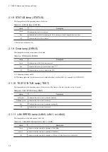
2.1.12 LAN LINK/ACT lamp (LAN0, LAN1, or LAN2)
This lamp indicates the link status and communication status of the LAN.
Table 2‒7: LAN LINK/ACT lamp (LAN0, LAN1, or LAN2)
Lamp
Description
Solid green
Indicates that a link has been established.
Blinking green
Indicates that network data is being sent or received. The blinking interval varies depending on the
network traffic.
Off
Indicates that a link has not been established.
2.1.13 DisplayPort connectors (DISPLAY1 and DISPLAY2)
These connectors are for connecting cables from display devices.
2.1.14 External Contact connector (EXT)
This connector is used as a general-purpose contact I/O interface.
2.1.15 USB 3.0 ports (USB1 and USB2)
These connectors are for connecting USB devices.
2. CE50-10 Names and Functions of Parts
15
Summary of Contents for CE50-10
Page 1: ...Hitachi Industrial Edge Computer CE50 10 Instruction Manual CC 65 0171 ...
Page 10: ......
Page 23: ...Figure 1 6 Attaching mounting brackets 4 1 Installing the CE50 10 7 ...
Page 26: ......
Page 38: ......
Page 42: ...4 2 5 Connection diagram Figure 4 2 Connection diagram 4 External Contact Functions 26 ...
Page 44: ......
Page 87: ... sudo etc init d netfilter persistent save 5 Configuring Software Environment 71 ...
Page 117: ...version information 13 Log out from the unit exit 5 Configuring Software Environment 101 ...
Page 148: ......
Page 149: ...7 Maintaining the CE50 10 This chapter describes maintenance of the CE50 10 133 ...
Page 157: ...8 Troubleshooting This chapter describes troubleshooting of the CE50 10 141 ...
Page 162: ...8 1 14 Cannot turn off the power to the unit Please contact us 8 Troubleshooting 146 ...


