


--- 10 ---
8-3. Lubrication Points and Types of Lubricant
Anytime the Gear Cover [2] is disassembled, thoroughly clean out the old grease and insert 15 grams (.53 oz) of
new grease (Nippeko grease (SEP-3A) is recommended) prior to reassembly.
8-4. Tightening Torques
(1) Tapping Screws D5 x 30 [1] ................................................... 2.9 0.5 N
•
m (30 5 kgf
•
cm, 2.2 0.4 ft-lbs.)
(2) Tapping Screws (W/Flange) D4 [48] [51] .............................. 2.0 0.5 N
•
m (20 5 kgf
•
cm, 1.5 0.4 ft-lbs.)
(3) Hex. Socket Set Screw M8 x 20 [3] ....................................... 8.8 1.0 N
•
m (90 10 kgf
•
cm, 6.3 0.7 ft-lbs.)
(4) Brush Cap [41] ...................................................................... 1.0 0.5 N
•
m (10 5 kgf
•
cm, 0.7 0.4 ft-lbs.)
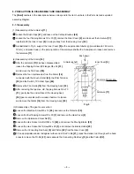
(6) When installing the Stator [14] into the Housing Ass'y [32], insert it while taking care of the placement of the
internal wires of the Stator [14] as indicated in Fig. 8. Connect the four internal wires of the Stator [14] with
the parts indicated in Fig. 8.
Connect to the Brush Holder [43]
(on the same side as the Name Plate [33]).
Connect the Cord [52] with the Pillar
Terminal [39].
Connect to the Switch (1P Solder Type) [44].
(When using the Noise Suppressor [36],
connect to the Switch (1P Solder Type) [44] with
the Terminal [46] of the Noise Suppressor [36].
Connect to the Brush Holder
[43] (on the same side as
the Hitachi Label [40]).
Fig. 8
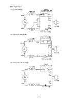
(7) When connecting the Earth Terminal [34] to the internal wire (the middle wire among three) of the Noise
Suppressor [36], strip the insulation sheath on the internal wire by about 6 mm and press-connect it together
with the Earth Terminal [34] with a clamping tool on the market.
Solderless connection
Fig. 9
Summary of Contents for CE 16SA
Page 21: ......


