background image

S

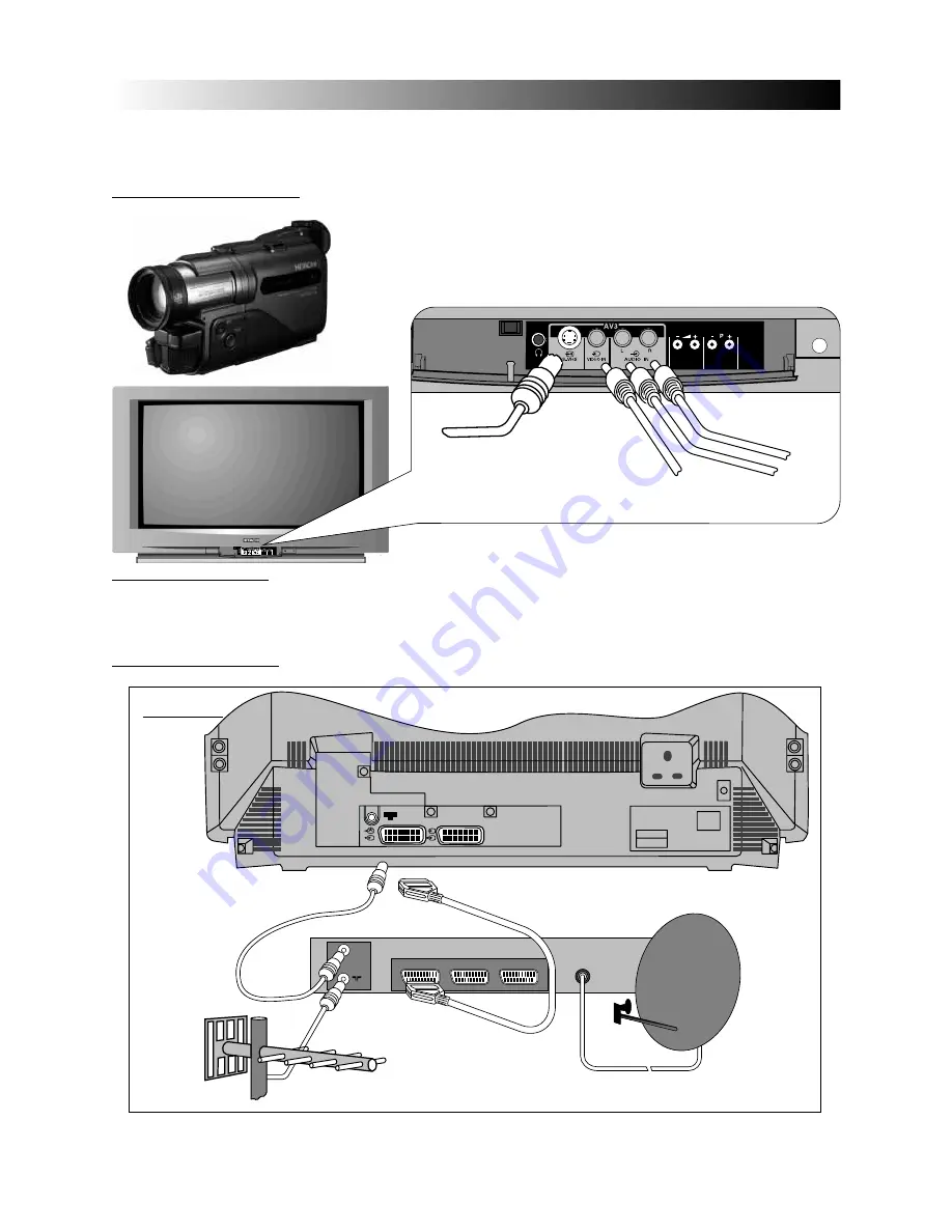
SATELLITE CONNECTION: There are two basic methods of connecting a satellite system to your TV. Method 1 explains
connection of satellite equipment directly to the TV, where as Method 2 refers to connection via a VCR.

METHOD 1

CAMCORDER CONNECTION:  Connecting a camcorder to your TV is simple. Firstly, identify the type of camcorder and it’s

connecting plugs. If it is a standard 8mm type camera then it is likely to have ‘RCA’
type sockets. If, however, you have S-VHS or Hi8 type camera then this may have a
S-VHS/Hi8 plug and will have to be placed in the corresponding S-VHS/Hi8 socket
on the TV.  Open the front control panel door on the TV, and connect your equip-
ment as shown in the illustration below. Switch your TV on, and repeatedly press the
TV/AV button (Nº9) on your handset until AV3 is displayed on-screen. Now begin

External Equipment Connection

External Equipment Connection

Your TV has various input sockets for external equipment such as Video Cassette Recorders, Satellite Receiver/Decoder,
Camcorders, Computer Equipment etc.. Equipment that is connected temporarily i.e. Camcorders can be connected via the
front control panel input sockets. However, equipment such as VCR’s and Satellite IRD’s, that are more or less permanently
connected to your TV, are connected via the AV1 or AV2 scart sockets on the rear of the TV. 

*S-VHS/Hi8 Plug

Video In
*‘RCA’ Plug

Audio In

(Right)

‘RCA’ Plug

Audio In

(Left)

‘RCA’ Plug

*Scart Lead to AV1 on TV

Aerial 

RF lead to Aerial

Satellite LNB lead

RF lead from
Satellite to TV

COMPUTER EQUIPMENT: If computer equipment is to be connected to this TV, use AV1 as the RGB input socket located
on the rear of the TV.
PLEASE NOTE:  Prolonged use of computer equipment or games on this TV may cause permanent damage to
your picture tube. To avoid such damage, reduce the brightness and contrast to an acceptable minimum level and
limit the duration of equipment operation.

AV3

Page19

Page19

* If your camcorder has both S-VHS/Hi8 and ‘RCA’ type sockets,
then connect the S-VHS/Hi8 socket only.

Summary of Contents for C24W1TN

Page 1: ...C24W1TN C28W1TN C32W1TN C24W410SN WIDE SCREEN COLOUR TELEVISION INSTRUCTION BOOKLET ...

Page 2: ...emote control handset While following this manual fold out this section this will enable you to easily reference between the manual and the remote control handset You should enjoy many years of trouble free operation from your TV Take some time to read the Operating Guide thoroughly and if you encounter any difficulty firstly refer to the Trouble Shooting guide at the rear of this manual If in the...

Page 3: ...ayout 1 2 3 RECALL HOLD 7 8 9 UPDATE PLAY TV TEXT CLE 921A CLE 921A MUTE STOP F FWD REW EXP 16 9 P INDEX EPG MENU P 0 REVEAL SWAP CH 4 5 6 SUBTITLES TV AV I II V TIME 1 2 3 4 5 6 7 8 9 10 11 12 13 14 15 16 17 18 19 20 21 22 23 24 25 26 27 ...

Page 4: ...iew The EPG function is not available on this model Please Note The following VCR controls operate Hitachi VCR equipment only 12 Stand by Button Used to switch the VCR on and off for short periods of time 13 Stop Button Press to stop the VCR tape 14 Rew Button Press to rewind a VCR tape 15 Play Button Press to play a VCR tape 16 F Fwd Button Press to fast forward a VCR tape 17 P Cursor Down When i...

Page 5: ...ipment DO NOT use makeshift stands and NEVER fix legs with wood screws to ensure complete safety always fit the manufacturers approved stand or legs with the fixings provided according to the instructions DO NOT allow electrical equipment to be exposed to rain or moisture NEVER let anyone especially children push anything into holes slots or any other opening in the case this could result in a fat...

Page 6: ...s since this can result in leakage or in extreme cases fire or explosion ALWAYS Store unused batteries in their packaging and away from metal objects which may cause a short circuit resulting in leakage or in extreme cases fire or explosion NEVER Never dispose of batteries in fire as this can cause an explosion Respect the environment always dispose of batteries in an environmentally friendly mann...

Page 7: ...e guidelines could result in serious overheating of your TV or in extreme cases even fire TV Installation TV Installation Step 2 TV only installation S OUT Step 3 Installation via a VCR Aerial RF Lead Aerial RF Socket Aerial RF Lead Aerial RF Socket VCR Optional Scart Lead TV to VCR A scart lead should be fitted between your TV and VCR to enhance your picture and sound quality Scart leads are esse...

Page 8: ...t sockets AV1 and AV2 The RF aerial socket is permanently connected to an RF source i e an aerial antenna shown on Page 7 The scart sockets are used to connect external equipment such as VCR s Satellite Receivers Decoder etc Connection of this equipment is explained in greater detail in the EXTERNAL EQUIPMENT CONNECTION section S S RF Aerial Input Socket Scart Socket AV1 Scart Socket AV2 SWITCHING...

Page 9: ...der 1 BBC1 2 BBC2 3 ITV 4 CH4 S4C 5 CH5 subject to availability 6 Cable Satellite broadcasts Alternatively if you are familiar with local broadcasting frequency or CH numbers then these can be entered manually Please refer to the Manual Tuning Procedure section of this manual IMPORTANT NOTE If you have a VCR or a Satellite receiver connected to this TV please ensure that they are switched on befor...

Page 10: ...or 21 to select PROGRAM SORT and press cursor key 18 or 19 to enter Use cursor key 17 or 21 to select INSTALL and press cursor key 18 or 19 to enter Press and HOLD the MENU key 20 until Main Menu with INSTALL is shown top right Automatic T Automatic Tuning cont uning cont Page10 Page10 Main Menu Picture Audio Sound Mode Feature Install Install Autotune Manual Tune Program Sort Language Program Sor...

Page 11: ...This section deals with locating broadcasting stations using the Search Tuning and combined Fine Tuning facility Fine Tuning may be required after Search or Automatic Tuning is complete Use cursor keys 17 18 19 and 21 to highlight frequency bar of programme Nº to Search Tune The Manual Tune menu is displayed bottom right Select Manual Tune and press cursor keys 18 or 19 to enter Manual Tune menu S...

Page 12: ...A AV Prog Nºs V Prog Nºs Press the CH key 23 on your handset once the column changes RED to indicate selection Use cursor keys 17 18 19 or 21 to highlight the frequency of the program number you wish to enter Press and HOLD MENU key 20 and select INSTALL Select MANUAL TUNE from INSTALL menu Repeat above to enter other AV sockets or repeatedly press MENU key 20 to store and exit to TV mode Once hig...

Page 13: ...To add or change program names follow the simple step by step guide below Program Naming Program Naming Press the CH key 23 the first digit will blink now use cursor keys 17 21 to scroll through all the characters Use cursor keys 17 18 19 or 21 to highlight the Program Name you wish to assign or change Press and HOLD MENU key 20 and select INSTALL Select MANUAL TUNE from INSTALL menu Page13 Page13...

Page 14: ...rols as necessary once complete press MENU button key 20 to exit To obtain the MORE sub menu highlight MORE and press cursor keys 18 or 19 to enter Highlight the control to be adjusted using cursor keys17 or 21 The PICTURE menu middle right is displayed Picture and Picture and Audio Controls Audio Controls Picture settings are controlled via the TV s on board Menu system These levels have already ...

Page 15: ... Bass Boost These settings have already been preset at the factory however your personal listening tastes may differ from those set Please follow the guide below for adjustment and setting Use GREEN colour coded key 25 to select AUDIO or use keys 17 21 to select and key 18 or 19 to enter Press the MENU key 20 on your handset The Main Menu is displayed Picture and Picture and Audio Controls Audio C...

Page 16: ... Default Use BLUE colour coded key 22 to select FEATURE or use cursor keys 17 21 to select and cursor key 18 or 19 to enter Press the MENU key 20 on your handset The Main Menu is displayed Select Scart2 Auto Mode and adjust the controls between AV and SAV with cursor keys 18 and 19 Press the MENU key 20 on your handset The Main Menu is displayed Select Sleep Timer and enter the time value with cur...

Page 17: ...s sound when a mono signal is found Some stereo signals can become poor in adverse weather conditions and mono should be selected to avoid poor sound Use the I IIu key Nº25 to switch to mono the sym bol below appears when switched Monaural Monaural Pseudo stereo creates an ambient sound from mono signals imitating that of stereo sound Use the key Nº24 to select Pseudo Stereo When selected the symb...

Page 18: ...reen to it s original setting Panoramic mode emulates that of a Wide Screen broadcast for 4 x 3 trans missions This is achieved by maintaining the proportions of the centre of the screen while extending the images on the sides of the screen example 4 example 5 example 6 When viewing pictures in the 14 9 Letterbox mode example 6 thin black bars appear at the top and bottom of the screen and images ...

Page 19: ... input sockets for external equipment such as Video Cassette Recorders Satellite Receiver Decoder Camcorders Computer Equipment etc Equipment that is connected temporarily i e Camcorders can be connected via the front control panel input sockets However equipment such as VCR s and Satellite IRD s that are more or less permanently connected to your TV are connected via the AV1 or AV2 scart sockets ...

Page 20: ...ill then be switched to the headphones 3 5mm Headphone jack socket a suitable adaptor is required for larger headphone plugs NOTE S VHS video equipment should be connected to the AV2 Scart socket located on the rear of the TV A dedicated program number may then be assigned to AV2 allowing you easier access to view external equipment broadcasts How to assign AV sockets to dedicated program numbers ...

Page 21: ...21 you may step up or down a page respectively If a mistake occurs while entering a number then simply re enter the desired number FAVOURITE PAGE OPTIONS The TV is capable of storing up to 4 favourite pages These pages could be your favourite sport or TV page etc and are accessed by pressing one of the colour coded keys keys 9 22 24 and 25 on your handset To enter a favourite page first access the...

Page 22: ...one Transmitter problems Check with local Operator Aerial has moved out of position Re align aerial TV not tuned correctly Re tune or Fine tune TV Adverse weather conditions None Transmitter problems Check with local Operator Magnetic interference from electrical Check devices for shielding or mechanical motors fluorescent and renew if necessary or lights portable radios etc move further from TV T...

Page 23: ...han an Hitachi authorised engineer iii The product serial number has not been removed or altered This guarantee does not apply to product acquired secondhand or for commercial or communal use This guarantee does not cover the replacement of exhausted batteries the adjustment of user controls or aerial alignment Any parts replaced under this guarantee shall become the property of Hitachi Home Elect...

Page 24: ...INPUT STATUS BLANKING INPUT GROUND VIDEO GROUND VIDEO COMPOSITE VIDEO OUTPUT COMPOSITE VIDEO INPUT GROUND 1 2 3 4 5 6 7 8 9 10 11 12 13 14 15 16 17 18 19 20 21 1 2 3 4 5 6 7 8 9 10 11 12 13 14 15 16 17 18 19 20 21 PIN No FUNCTION AUDIO OUT RIGHT AUDIO INPUT RIGHT AUDIO OUT LEFT GROUND AUDIO NOT USED AUDIO INPUT LEFT NOT USED SWITCHING INPUT NOT USED NOT USED NOT USED NOT USED CHROMINANCE GROUND NO...

Page 25: ... factors should also be considered when operating your TV Reducing volume settings to sensible levels can reduce power consumption as well as reducing noise pol lution and reducing the contrast can also provide a more pleasing picture in lower ambient lighting conditions as well as reducing power consumption Hitachi Home Electronics Europe Ltd Manufacturing Site in Wales is a BSI Registered Compan...

Page 26: ......

Page 27: ......

Page 28: ... ITALY Tel 39 02 487861 Tel 39 02 38073415 Servizio Clienti Fax 39 02 48786381 2 Email customerservice italy hitachi eu com HITACHI Europe AB Box 77 S 164 94 Kista SWEDEN Tel 46 0 8 562 711 00 Fax 46 0 8 562 711 13 Email csgswe hitachi eu com HITACHI EUROPE S A S Lyon Office B P 45 69671 BRON CEDEX FRANCE Tel 04 72 14 29 70 Fax 04 72 14 29 99 Email france consommateur hitachi eu com HITACHI EUROPE...

Reviews: