background image

16

English

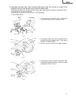
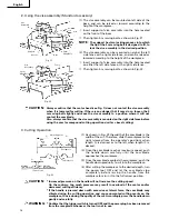
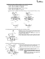
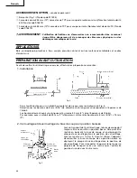
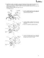
  2. Using the vise assembly (Standard accessory)

(1) The vise assembly can be mounted on left side of the

base, and can be raised or lowerd according to the
height of the workpiece.

q

Insert support of vise assembly into the hole located
on the front of the base.

w

Then tighten 5 mm wing bolt as shown in Fig. 21.

NOTE:

The support has two locking grooves into which
the tip of the 5 mm wing bolt is designed to fit, to
lock the vise assembly in the desired position.

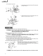
(2) The vise assembly can be mounted on eigher the left

side fence or the right side fence, and can be raised or
lowered according to the height of the workpiece.

q

Insert support of vise assembly into the hole located
on either the left side fence or the right side fence.

w

Then tighten 5 mm wing bolt as shown in Fig. 22.

CAUTION:

Always confirm that the motor head (see Fig. 1) does not contact the vise assembly
when it is lowered for cutting. If there is any danger that it may do so, loosen the 5
mm wing bolt slightly and move the vise assembly to a position where it will not
contact the saw blade.
Also, always confirm that the vise assembly is mounted on the right side fence before
using the saw for compound cutting operations (miter + bevel cutting).

  3. Cutting Operation

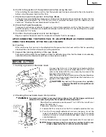
(1) As shown in Fig. 23 the width of the saw blade is the

width of the cut. Therefore, slide the workpiece to the
right (viewed from the operator’s position) when
length 

b

 is desired, or to the left when length 

a

 is

desired.

(2) Once the saw blade reaches maximum speed, push

the handle down carefully until the saw blade
approaches the workpiece.

(3) Once the saw blade contacts the workpiece, push the

handle down gradually to cut into the workpiece.

(4) After cutting the workpiece to the desired depth, turn

the power tool OFF and let the saw blade stop
completely before raising the handle from the
workpiece to return it to the full retract position.

CAUTION:

* Increased pressure on the handle will not increase the cutting speed.

On the contrary, too much pressure may result in overload of the motor and/or
decreased cutting efficiency.

* If the handle is pressed down with excessive or lateral force, the saw blade may

vibrate during the cutting operation and cause unwanted cutting marks on the
workpiece, thus reducing the quality of the cut. Accordingly, press the handle down
gently and carefully.

WARNING:

* Confirm that the trigger switch is turned OFF and the power plug has been removed

from the receptacle whenever the tool is not in use.

5 mm
Wing Bolt

Vise
Assembly

Support

Fig. 21

Fence

Fig. 22

Groove

Base

5 mm
Wing Bolt

Vise
Assembly

(Front View)

Adjusting Line

a

b

Marking
(pre-marked)

Marking
(pre-marked)

a

b

a

b

Table Insert

Fig. 23

Workpiece

Summary of Contents for C 10FC2

Page 1: ...es blessures corporelles Ce mode d emploi contient d importantes informations à propos de la sécurité de ce produit Prière de lire et d assimiler ce mode d emploi avant d utiliser l outil motorisé Garder ce mode d emploi à la disponibilité des autres utilisateurs avant qu ils utilisent l outil motorisé MANUAL DE INSTRUCCIONES E INSTRUCCIONES DE SEGURIDAD ADVERTENCIA La utilización inapropiada e in...

Page 2: ...S SUR 27 UTILISATION ET ENTRETIEN NOM DES PIÈCES 28 SPÉCIFICATIONS 29 Page ACCESSOIRES 29 ACCESSOIRES STANDARD 29 ACCESSOIRES EN OPTION 30 APPLICATIONS 30 PRÉPARATION AVANT L UTILISATION 30 AVANT L UTILISATION 32 AVANT LA COUPE 33 APPLICATIONS PRATIQUES 35 INSTALLATION ET RETRAIT DE LA LAME 40 ENTRETIEN ET INSPECTION 41 SERVICE APRÈS VENTE ET RÉPARATIONS 42 TABLE DES MATIERES Página ACCESORIOS 49 ...

Page 3: ...ize the risk of electric shock or other personal injury In particular always comply with the following safety rules 1 ALWAYS KEEP GUARDS IN PLACE and in working order 2 ALWAYS REMOVE ADJUSTING KEYS AND WRENCHES BEFORE STARTING TOOL Always confirm that all keys and adjusting wrenches have been removed from the tool before it is turned on 3 ALWAYS KEEP WORK AREA CLEAN Avoid injuries by not clutterin...

Page 4: ...plete stop Always turn the power off when the tool is not in use Always unplug the power cord when the tool is not in use 20 This tool was not designed to be used for mass production applications and should not be used in mass production environments 21 When servicing this tool use only authorized replacement parts 22 Apply 115 volts AC only to this tool Applying the wrong voltage or applying DC p...

Page 5: ...assembly 23 The operating instructions provided with the tool shall direct the user to secure the tool to supporting structure if during normal operation there is a tendency for the tool to tip over slide or walk on the supporting surface DON Ts NEVER VIOLATE THE FOLLOWING RULES TO ASSURE SAFE USE OF THIS TOOL 1 Never operate the POWER TOOL unless you fully understand the operating instructions co...

Page 6: ...55mm 9 No load speed is 4900rpm REPLACEMENT PARTS When servicing use only identical replacement parts Repairs should be conducted only by a Hitachi authorized service center USE PROPER EXTENSION CORD Make sure your extension cord is in good condition When using an extension cord be sure to use one heavy enough to carry the current your product will draw An undersized cord will cause a drop in line...

Page 7: ...tem has no external grounding you must still follow the normal electrical safety precautions given in this Instruction Manual including not using the power tool in wet environments To keep the double insulation system effective follow these precautions Only HITACHI AUTHORIZED SERVICE CENTER should disassemble or assemble this power tool and only genuine HITACHI replacement parts should be installe...

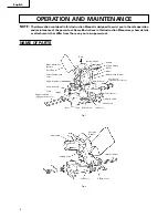
Page 8: ... that differ from those on your own power tool NAME OF PARTS Fig 1 Fig 2 Nameplate Clamp Lever Indicator Cutting Arm Spring Plate Table Insert Table Base Extension Wing Optional Accessory Fence Vise Assembly Angle Regulator Dust Bag Lever Blade Guard Metal Head Handle Trigger Switch Blade Blade Guard Plastic Stock Stop Optional Accessory Chip Deflector Indicator Miter Scale Miter Handle Button Swi...

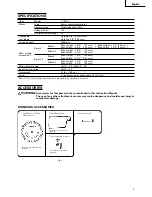
Page 9: ... Miter 45 Max Height 1 3 4 44 mm Max Width 3 1 2 89 mm Miter sawing range Left 0 45 Right 0 60 Bevel sawing range Left 0 45 Net weight 32 lbs 14 5 kg Cord 2 Conductor type cabtire cable 7 8 ft 2 4 m Note 11 16 17 mm thick spacer board is required to be attached to the fence ACCESSORIES WARNING Accessories for this power tool are mentioned in this Instruction Manual The use of any other attachment ...

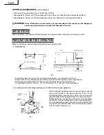
Page 10: ...meter bolts suitable in length for the thickness of the work bench Bolt length should be at least 2 50 mm plus the thickness of the work bench For example use 5 16 8 mm 3 75 mm bolts fot a 1 25 mm thick work bench 2 Locking and unlocking cutting arm in from the down position When transporting the power tool the cutting arm should always be locked in the down position This can be accomplished by lo...

Page 11: ...he followings 1 Assembly of lever q Push down on the handle see Fig 1 slightly and turn the lock plate to the unlocked position w The head will then move to the up position and the lever will be hanged freely in the down position as shown in Fig 7 e Remove special screw from the angle regulator r Insert special screw into hole at the end of lever and reassemble special screw into hole in angle reg...

Page 12: ...an cause a serious accident 3 Check the saw blade for visible defects Confirm that the saw blade is free of cracks or other visible damage 4 Confirm that the saw blade is attached securely to the power tool Using the supplied wrench tighten the bolt on the arbor shaft to secure the saw blade For details see Fig 34 a and Fig 34 b in the section on SAW BLADE MOUNTING AND DISMOUNTING 5 Check the blad...

Page 13: ...aw blade and check for deflection to confirm that the blade is not noticeably unstable otherwise vibrations might occur and cause an accident BEFORE CUTTING 1 Cutting a groove on the table insert A groove has to be cut in the table insert before starting operation Secure a piece of wood about 5 1 2 140 mm wide to the table with the vise assembly to prevent the breakage of the table insert After th...

Page 14: ...ting operation 1 Insert extension wing through first pair of holes on outside of base 2 Find the second pair of holes underneath the base Put U bracket over hole nearest to the front edge of the base 3 Insert extension wing through both the second pair of holes and U bracket Make sure the extension wing passes completely through the second pair of holes as shown in Fig 16 4 Tighten 6 mm bolt on U ...

Page 15: ...1 Switch operation The button switch is designed to prevent inadvertent operation of the power tool To operate the power tool it is necessary to first push the button switch as shown in Fig 20 The trigger switch will not operate unless the button switch has been pushed in When the trigger switch is released the power goes off and the button switch automatically returns to its initial position lock...

Page 16: ...tion 1 As shown in Fig 23 the width of the saw blade is the width of the cut Therefore slide the workpiece to the right viewed from the operator s position when length b is desired or to the left when length a is desired 2 Once the saw blade reaches maximum speed push the handle down carefully until the saw blade approaches the workpiece 3 Once the saw blade contacts the workpiece push the handle ...

Page 17: ...5 22 5 31 6 45 and 60 right and 15 22 5 31 6 and 45 left settings Check that the miter angle scale and the tip of the indicator are properly aligned Operation of the power tool with the miter angle scale and indicator out of alignment or with the miter handle not properly tightened will result in poor cutting precision 5 Bevel cutting procedures 1 Loosen the clamp lever and bevel the saw blade to ...

Page 18: ...ittle to the right and left to stabilize the position and to properly align the miter angle scale and the tip of the indicator before the operation starts For bevel cut setting Move handle on bevel section to the right and left and check that the position is stable and that the bevel angle scale and the tip of the indicator are properly aligned Then tighten the clamp lever Type of To process crown...

Page 19: ...workpiece as shown in Fig 32 When cutting aluminum materials coat the saw blade with cutting oil non combustible to achieve smooth cutting and a fine finish 9 How to use the dust bag Standard accessory 1 When the dust bag has become full of sawdust dust will be blown out of the dust bag when the saw blade rotates Check the dust bag periodically and empty it before it becomes full 2 During bevel an...

Page 20: ...tation direction of the blade guard metal are properly matched 6 Thoroughly clean arbor collar and the bolt and install them onto the arbor shaft 7 Press in the spindle lock and tighten the bolt by turning it to the left by wrench as indicated in Fig 34 b CAUTION Confirm that the spindle lock has returned to the retract position after installing or removing the saw blade Tighten the bolt so it doe...

Page 21: ...carbon brush have been installed After the first check examine them after each about 10 hours of use until such time that replacement is necessary When the carbon on either brush is worn to 3 16 5 mm in length or if either spring or shunt wire is burned or damaged in any way replace both carbon brushes see Fig 35 If the carbon brushes are found serviceable after removing reinstall them in the same...

Page 22: ...on of vise assembly Rotary portion of table and base 7 Cleaning Periodically remove chips dust and other waste material from the surface of the power tool especially from the inside of the blade guard plastic with a damp soapy cloth To avoid a malfunction of the motor protect it from contact with oil or water SERVICE AND REPAIRS All quality power tools will eventually require servicing or replacem...

Page 23: ...NSIGNES DE SÉCURITÉ RELATIVES AUX OUTILS ÉLECTRIQUES LIRE TOUS LES AVERTISSEMENTS ET TOUTES LES INSTRUCTIONS D UTILISATION DU MANUEL AVANT DE METTRE L OUTIL EN SERVICE OU DE L ENTRETENIR AVERTISSEMENT Lorsqu on utilise l outil électrique prendre toutes les précautions nécessaires pour éviter au maximum tout risque de choc électrique ou autre blessure physique En particulier toujours respecter les ...

Page 24: ... outil ou en cas de contact accidentel avec la lame de scie 17 TOUJOURS VÉRIFIER SI L OUTIL A DES PIÈCES ENDOMMAGÉES AVANT DE L UTILISER Toujours vérifier si la protection et les autres composants sont endommagés avant d utiliser l outil pour s assurer qu ils fonctionneront correctement Vérifier si toutes les pièces mobiles sont bien alignées non voilées ou toute autre condition qui pourrait entra...

Page 25: ...r la garde pour qu elle ne risque pas d être éjectée de la table et de provoquer des blessures 10 Pendant une coupe d onglet ou de biseau toujours attendre que la lame ait complètement cessé de tourner avant de la relever 11 Toujours faire un essai avant d utiliser la scie pour un nouvel usage 12 Toujours manipuler la scie avec soin lorsqu on la démonte ou qu on la monte 13 Toujours vérifier qu il...

Page 26: ... OUTIL ELECTRIQUE si le logement en plastique ou la poignée sont déformés ou fendillés 14 Ne jamais utiliser l OUTIL ELECTRIQUE à proximité d un liquide ou d un gaz inflammable car les étincelles pourraient provoquer une explosion 15 Ne jamais nettoyer les composants en plastique avec des solvants car cela risquerait de dissoudre le plastique 16 Ne jamais faire fonctionner la scie si les protectio...

Page 27: ... l eau ou à proximité d eau ni dans un environnement susceptible de provoquer un choc électrique DOUBLE ISOLATION POUR UN FONCTIONNEMENT PLUS SUR Pour assurer un fonctionnement plus sûr de cet outil électrique HITACHI a adopté une conception à double isolation Double isolation signifie que deux systèmes d isolation physiquement séparés ont été utilisés pour isoler les matériaux conducteurs d élect...

Page 28: ...tentionnellement supprimés à des fins d illustration NOM DES PIÈCES Plaque signalétique Levier de serrage Indicateur Bras de coupe Plaque de ressort Plaque d insertion Table Socle Servante accessoire en option Garde Sac à poussière Levier Protection de la lame métallique Tête Poignée Gâchette Lame Protection de lame en plastique Butée de matériau accessoire en option Déflecteur de copeaux Indicate...

Page 29: ...et 45 Hauteur max 44 mm 1 3 4 Largeur max 89 mm 3 1 2 Plage de coupe d onglet Gauche 0 45 Droite 0 60 Plage de coupe en biseau Gauche 0 45 Poids net 14 5 kg 32 lbs Cordon Câble sous gaine de caoutchouc à 2 conducteurs 2 4 m 7 8 ft Remarque Une plaque d entretoise de 17 mm 11 16 d épaisseur devra être fixée à la garde ACCESSOIRES AVERTISSEMENT Les accessoires pour cet outil électrique sont mentionn...

Page 30: ...tre de la longueur correspondant à l épaisseur de l établi Les boulons devront avoir une longueur d au moins 50 mm 2 plus l épaisseur de l établi Par exemple avec un établi de 25 mm 1 d épaisseur utiliser des boulons de 8 mm 5 16 75 mm 3 2 Verrouillage et déverrouillage du bras de coupe en position baissée Lors du transport de l outil électrique le bras de coupe doit toujours être verrouillé en po...

Page 31: ...age du levier q Pousser la poignée légèrement vers le bas voir Fig 1 et tourner la plaque de verrouillage dans la position de déverrouillage w La tête se déplace en position haute et le levier pend librement en position basse comme montré sur la Fig 7 e Retirer la vis spéciale du régulateur d angle r Insérer la vis spéciale dans le trou à l extrémité du levier et la revisser dans le trou du régula...

Page 32: ...ave accident 3 Vérifier s il y a des défauts visibles sur la lame S assurer qu il n y a ni fissures ni dommages visibles sur la lame 4 Vérifier que la lame est solidement fixée sur l outil électrique A l aide de la clé fournie serrer le boulon de l arbre pour fixer la lame Pour les détails voir les Fig 34 a et 34 b de la section relative au MONTAGE ET DEMONTAGE DE LA LAME DE SCIE 5 Vérifier le fon...

Page 33: ...as d instabilité évidente sinon cela risque de provoquer des vibrations et un accident AVANT LA COUPE 1 Coupe d une encoche dans la plaque d insertion Avant de mettre l outil en service il faudra découper une encoche dans la plaque d insertion Fixer un morceau de bois d environ 140 mm 5 1 2 de large sur la table avec l ensemble d étau pour éviter que la plaque d insertion ne se rompe Mettre l outi...

Page 34: ...es pièces de grande dimension pendant l opération de coupe 1 Insérer la servante à travers la première paire de trous à l extérieur du socle 2 Trouver la seconde paire de trous sous le socle Mettez le support en U sur le trou le plus près du côté avant du socle 3 Insérer la servante à travers la seconde paire de trous et dans le support en U S assurer que la servante passe complètement dans la sec...

Page 35: ...eur Le bouton de blocage est conçu pour empêcher tout fonctionnement accidentel de l outil électrique Pour faire marcher l outil il faut d abord appuyer sur le bouton de blocage comme montré sur la Fig 20 La gâchette ne pourra pas être utilisée tant que le bouton de blocage n est pas poussé Quand la gâchette est relâchée l outil se met hors tension et le bouton de blocage revient automatiquement s...

Page 36: ...droit de la garde avant d utiliser la scie pour couper un matériau onglet et coupe en biseau 3 Coupe 1 Comme indiqué à la Fig 23 la largeur de la lame est la largeur de coupe En conséquence glisser la pièce vers la droite vue de la position de l opérateur pour obtenir la longueur b et sur la gauche pour obtenir la longueur a 2 Quand la lame a atteint sa vitesse maximale abaisser doucement la poign...

Page 37: ...a poignée de coupe d onglet à fond REMARQUE Des crans positifs sont prévus à droite et à gauche du réglage central de 0 15 22 5 31 6 45 et 60 à droite et 15 22 5 31 6 et 45 à gauche Vérifier que l échelle d angle d onglet et que la pointe de l indicateur sont alignées correctement Le fonctionnement de l outil électrique avec l échelle d angle d onglet et l indicateur non alignés ou avec la poignée...

Page 38: ...la droite ou vers la gauche pour stabiliser la position et aligner correctement l échelle d onglet et l extrémité de l indicateur avant de commencer le travail Réglage d une coupe de biseau Déplacer la poignée de la section de biseau vers la droite et vers la gauche et vérifier que la position est stable et que l échelle d angle et l extrémité de l indicateur sont alignés correctement Puis serrer ...

Page 39: ...Fig 31 8 Coupe de matériaux qui se déforment facilement par exemple une feuille d aluminium Les matériaux comme l aluminium en feuille se déforment facilement quand ils sont serrés trop fort dans un étau Cela ne permettra pas une bonne coupe et risque de provoquer une surcharge du moteur Pour couper ce genre de matériaux utiliser une planche de bois pour protéger la pièce comme indiqué à la Fig 32...

Page 40: ...tion de l arbre du couteau sur la position supérieure 3 Appuyer sur le verrou d axe et desserrer le boulon avec une clé Le boulon ayant un filetage à gauche le desserrer en le tournant vers la droite comme indiqué à la Fig 34 b REMARQUE S il n est pas facile d enfoncer le verrou d axe pour verrouiller l arbre tourner le boulon à l aide de la clé à douille tout en appuyant sur le verrou d axe L arb...

Page 41: ...harge du moteur ATTENTION Ne jamais utiliser de lame émoussée Si la lame est émoussée sa résistance à la pression de la main appliquée par la poignée de l outil a tendance à augmenter ce qui rend le fonctionnement de l outil électrique peu sûr 2 Inspecter les balais carbone Fig 35 et Fig 36 Les balais carbone du moteur sont des pièces consommables Si les balais en carbone sont usés le moteur risqu...

Page 42: ... enfants 6 Graissage Graisser les surfaces de glissement suivantes une fois par mois pour maintenir l outil électrique en bon état de marche pendant longtemps voir Fig 1 et Fig 2 Il est recommandé d utiliser une huile de machine Points de graissage Section rotative du régulateur d angle Section rotative de l ensemble d étau Section rotative de la table et du socle 7 Nettoyage Enlever périodiquemen...

Page 43: ...n esencial SEGURIDAD NORMAS DE SEGURIDAD PARA LAS HERRAMIENTAS ELÉCTRICAS LEA TODAS LAS ADVERTENCIAS E INSTRUCCIONES DE OPERACIÓN DE ESTE MANUAL ANTES DE UTILIZAR ESTA HERRAMIENTA O DE REALIZAR TRABAJOS DE MANTENIMIENTO EN LA MISMA ADVERTENCIA Cuando utilice este herramienta eléctrica tome todas las precauciones necesarias para reducir al mínimo el riesgo de descargas eléctricas y demás lesiones E...

Page 44: ...RAMIENTA La caída de la herramienta o un contacto involuntario con la hora de sierra podría producir lesiones de gravedad 17 ANTES DE UTILIZAR LA HERRAMIENTA COMPRUEBE SI TIENE PARTES DAÑADAS Compruebe siempre si el protector y los demás componentes están dañados antes de utilizar la herramienta para asegurarse de que funcionen adecuadamente Compruebe si todas las partes móviles están adecuadament...

Page 45: ...s serias 10 Durante el corte de ingletes o en bisel espere siempre hasta que la hoja de sierra se haya parado completamente antes de levantarla 11 Realice siempre una prueba antes de intentar utilizar una hoja de sierra nueva 12 Maneje siempre la hoja de sierra con cuidado con la desmonte o monte 13 Antes de utilizar la sierra compruebe siempre si la pieza de trabajo está exenta de puntas y demás ...

Page 46: ...tilice nunca la HERRAMIENTA ELÉCTRICA si la envoltura de plástico o la empuñadura está rajada o deformada 14 No utilice nunca la HERRAMIENTA ELÉCTRICA cerca de líquidos ni gases inflamables porque las chispas podrían causar una explosión 15 No limpie nunca los componentes de plástico con disolventes porque el plástico podría disolverse 16 No utilice nunca la herramienta a menos que los protectores...

Page 47: ... ningún otro lugar en el que exista el riesgo de descargas eléctricas AISLAMIENTO DOBLE PARA OFRECER UNA OPERACIÓN MÁS SEGURA Para garantizar una operación más segura de esta herramienta eléctrica HITACHI ha adoptado un diseño de aislamiento doble Aislamiento doble significa que se han utilizado dos sistemas de aislamiento físicamente separados para aislar los materiales eléctricamente conductores...

Page 48: ... ilustración solamente NOMENCLATURA DE PARTES Placa de características Palanca de fijación Indicador Brazo cortador Placa de resorte Inserto de la mesa Mesa Base Aleta de extensión Accesorio opcional Escuadra de guía Conjunto de tornillo de carpintero Bolsa para el polvo Palanca Cabeza Empuñadura Interruptor de gatillo Hoja Protector de la hoja Plástico Retén Accesorio opcional Deflector de viruta...

Page 49: ...ura máx 89 mm 3 1 2 Anchura máx 146 mm 5 3 4 Anchura máx 92 mm 3 5 8 Dimensión Inglete de 45 Altura máx 70 mm 2 3 4 máxima Anchura máx 89 mm 3 1 2 de corte Bisel a la Inglete de 0 Altura máx 44 mm 1 3 4 derecha Anchura máx 130 mm 5 1 8 de 45 Inglete de 45 Altura máx 44 mm 1 3 4 Anchura máx 89 mm 3 1 2 Margen de corte en bisel 0 45 a la izquierda 0 60 Margen de corte en bisel 0 45 a la izquierda Pe...

Page 50: ...4 Seleccione pernos de 8 mm de diámetro 5 16 de un largo adecuado para el espesor del banco de trabajo El perno deberá ser de por lo menos 50 mm 2 más largo que el espesor del banco de trabajo Por ejemplo para un banco de trabajo de 25 mm 1 de espesor utilice pernos de 8 mm 5 16 75 mm 3 2 Bloqueo y desbloqueo del brazo cortador en desde la posición inferior Cuando transporte la herramienta eléctri...

Page 51: ...la figura 1 Conjunto de palanca q Presione ligeramente la manivela hacia abajo véase Fig 1 y gire la placa de bloqueo a la posición de desbloqueo w La cabeza se moverá entonces a la posición superior y la palanca colgará libremente en la posición inferior tal como se observa en la Fig 7 e Extraiga el tornillo especial del regulador de ángulo r Inserte el tornillo especial en el orificio del extrem...

Page 52: ...Compruebe si la hoja de sierra posee defectos visibles Confirme que la hoja de sierra esté exenta de rajas y de otros defectos visibles 4 Confirme que la hoja de sierra esté fijada con seguridad a la herramienta eléctrica Utilizando la llave suministrada apriete el perno sobre el eje de husillo para asegurar la hoja de sierra Para los detalles consulte la Fig 34 a y la Fig 34 b en la sección MONTA...

Page 53: ...OPIADO COMPRUEBE LA OPERACIÓN DE LA HERRAMIENTA DE LA FORMA SIGUIENTE 10 Operación de prueba Después de haber confirmado que no se ha olvidado de nada ponga en funcionamiento la herramienta eléctrica y confirme que no haya ninguna anormalidad antes de intentar realizar la operación de corte 11 Inspeccione la estabilidad de rotación de la hoja de sierra Para cortar con precisión gire la hoja de sie...

Page 54: ... no penetre en la mesa 3 Ángulo oblicuo Antes de expedirse de fábrica la herramienta eléctrica ha sido ajustada para ángulos de cortes en bisel de 0 y de 45 a la izquierda La posición y el ángulo de corte en bisel se pueden ajustar aflojando la contratuerca de 6 mm y cambiando la altura del perno de 6 mm El ángulo máximo de corte en bisel es de 45 4 Inmovilización de la pieza de trabajo ADVERTENCI...

Page 55: ...la base Sujete la herramienta por la empuñadura véase Fig 2 y no por el soporte de extensión 6 Retén para corte de precisión El retén es un accesorio opcional El retén permite realizar un corte continuo de precisión en longitudes de 236 mm a 460 mm 9 5 16 a 18 1 8 Para instalar el retén fíjelo al soporte con un perno de aletas de 6 mm tal como se observa en la Fig 18 APLICACIONES PRÁCTICAS ADVERTE...

Page 56: ...indica en la Fig 21 NOTA El soporte cuenta con dos ranuras de bloqueo en los cuales encaja la punta del perno de orejas de 5 mm para poder bloquear el conjunto del tornillo de carpintero en la posición deseada 2 El conjunto del tornillo de carpintero puede montarse en la escuadra de guía del lado izquierdo o bien en la escuadra de guía del lado derecho y puede elevarse o bajarse de acuerdo con la ...

Page 57: ...ocedimiento de corte de ingletes 1 Afloje la empuñadura lateral y tire de la placa de resorte 2 Ajuste la mesa hasta que el indicador se alinee con el ajuste deseado en la escala de ángulos de ingletes tal como se observa en la Fig 24 a 3 Reapriete la empuñadura lateral para asegurar la mesa en la posición deseada Para bloquear la mesa con precisión se ha provisto un buje de resina en el extremo d...

Page 58: ...a que la hoja de sierra podría entrar en contacto con el sujetador o con el tornillo de carpintero que asegura a la pieza de trabajo y causar lesiones o daños 7 Procedimientos de corte con moldura en vértice En la Fig 26 se muestran los tipos de moldura en vértice con ángulos de 38 y 45 Con respecto a las molduras en vértice típicas consulte la Fig 27 En la tabla siguiente se muestran los ajustes ...

Page 59: ...n vértice de tipo de 38 33 9 marca e Coloque la moldura en el vértice de forma que la superficie superior A de la Fig 26 entre en contacto con la escuadra de guía como se indica en la Fig 29 2 Ajuste para cortar molduras en vértice a los posiciones w y e de la Fig 27 consulte la Fig 30 incline la cabeza hacia la izquierda q Gire la mesa hacia la derecha y ajuste el ángulo de ingletes de la forma s...

Page 60: ...itar que se atasquen el conducto y el protector de la hoja metal Durante el corte en bisel se acumulará más polvo de lo normal MONTAJE Y DESMONTAJE DE LA HOJA DE SIERRA ADVERTENCIA Para evitar accidentes o lesiones suelte siempre el interruptor de disparo y desconecte el enchufe del cable de alimentación del tomacorriente antes de extraer o instalar la hoja de sierra 1 Montaje de la hoja de sierra...

Page 61: ...mm 9 Coloque el protector de la hoja plástico en la posición inferior 2 Desmontaje de la hoja de sierra Desmonte la hoja de sierra invirtiendo el proceso de montaje descrito en el párrafo 1 anterior La hoja de sierra podrá extraerse fácilmente después de levantar el protector del eje de la cortadora PRECAUCIÓN No intente instalar nunca hojas de sierra de diámetro superior a 255 mm 10 Instale siemp...

Page 62: ... ver si están flojos Reapriete los tornillos de montaje y cualquier pieza floja ADVERTENCIA Para evitar lesiones no utilice nunca la herramienta eléctrica si tiene alguna pieza floja 4 Inspección del funcionamiento del protector de la hoja Cada vez que utilice la herramienta pruebe previamente el protector de la hoja Fig 11 para verificar que se encuentra en buenas condiciones y que se mueve con s...

Page 63: ...as eléctricas de calidad necesitan el servicio o el reemplazo de piezas debido al desgaste por el uso para asegurarse de que solamente se utilicen piezas de remplazo autorizadas y el sistema de doble aislamiento todos los trabajos de servicio excepto el mantenimiento rutinario deberán realizarse SOLAMENTE EN UN CENTRO DE REPARACIONES DE HERRAMIENTAS ELÉCTRICAS AUTORIZADO POR HITACHI NOTA Las espec...

Page 64: ...64 PARTS LIST Model C 10FC2 ...

Page 65: ...65 MOTOR ASSEMBLY EXTENSION WING ASSEMBLY ...

Page 66: ...HEX BOLT M10 65 HEX BOLT M10 35 W WASHER HEX SOCKET SET SCREW M5 10 FENCE WING SCREW M5 20 HEX SOCKET SET SCREW M5 10 SCREW COMPRESSION SPRING PARTS NAME CLAMP LEVER HANDLE COLLAR WASHER 3 8 29 32 HEX SOCKET SET SCREW M6 12 PIVOT SHAFT BOLT M6 25 NUT M6 TILT BRACKET DRIVE SCREW D2 3 5 NUT CHUCK M8 FLAT WASHER M8 TABLE HANDLE BAR STEEL BALL D8 MACHINE SCREW M5 10 LOCATION SEAT MACHINE SCREW M4 8 TI...

Page 67: ...OLDER CARBON BRUSH BRUSH CAP ITEM No ITEM No Standard Accessories 701 702 703 PARTS NAME WRENCH TCT SAW BLADE 255MM D15 88 HOLE NT24 DUST BAG PARTS NAME ITEM No ITEM No Optional Accessories 907 908 909 910 PARTS NAME TCT SAW BLADE CROSS CUT 255MM D15 9 HOLE TCT SAW BLADE 255MM D15 9 HOLE HOLDER ASS Y INCLUD 906 910 WING BOLT 1 4 3 4 PARTS NAME STOCK STOP EXTENSION WING BOLT 1 4 5 8 U BRACKET ITEM ...

Page 68: ...aiwan Issued by Sinagawa Intercity Tower A 15 1 Konan 2 chome Minato ku Tokyo 108 6020 Japan Distributed by Hitachi Koki U S A Ltd 3950 Steve Reynolds Blvd Norcross GA 30093 Hitachi Koki Canada Co 6395 Kestrel Road Mississauga ON L5T 1Z5 ...

Reviews: