4
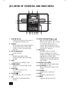
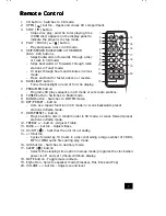
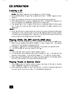
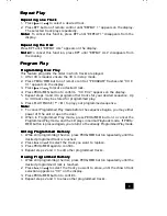
GENERAL OPERATION
GENERAL OPERATION
GENERAL OPERATION
GENERAL OPERATION
GENERAL OPERATION
M o u n t i n g t h e S y s t e m t o t h e w a l l
M o u n t i n g t h e S y s t e m t o t h e w a l l
M o u n t i n g t h e S y s t e m t o t h e w a l l
M o u n t i n g t h e S y s t e m t o t h e w a l l
M o u n t i n g t h e S y s t e m t o t h e w a l l
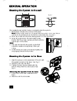
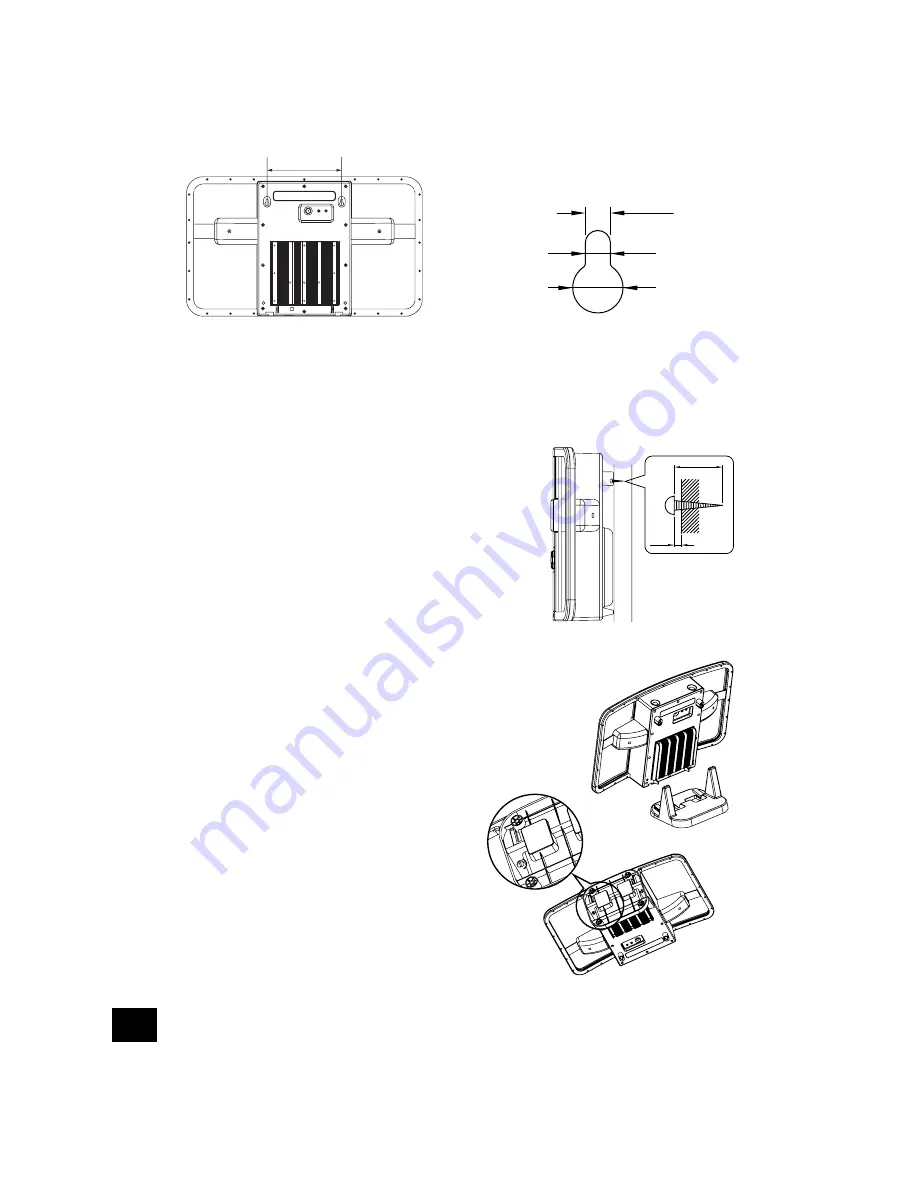
The supplied paper pattern helps you properly align the system.
1. Mark where to fasten the screws on the wall.
N o t e :
N o t e :
N o t e :
N o t e :
N o t e : Wall mounting screws are not supplied with this system. Use screws that are
suitable for the wall material and the hold size as illustrated here. (see fig 1)
2. Drive the screws into the wall, leaving about 1/2 inch extended.
3. Hang the system onto the protruding screws.
Ensure that the screws securely connect with the
narrow part of the holes.
N o t e :
N o t e :
N o t e :
N o t e :
N o t e :
•
The wall onto which the system is attached
should be capable of supporting 33lbs. per
screw.
•
Confirm that all screws are fastened tightly and
are properly fitted into the holes.
M o u n t i n g t h e S y s t e m t o I t s B a s e
M o u n t i n g t h e S y s t e m t o I t s B a s e
M o u n t i n g t h e S y s t e m t o I t s B a s e
M o u n t i n g t h e S y s t e m t o I t s B a s e
M o u n t i n g t h e S y s t e m t o I t s B a s e
1. Align the grooves on the underside of the unit with
the guides located on the base. See fig. 2.
2. Slide the unit onto the base.
3. Tighten the two screws underneath the
base to firmly hold the unit in place. See
fig. 3.
R e m o v i n g t h e S y s t e m f r o m I t s b a s e
R e m o v i n g t h e S y s t e m f r o m I t s b a s e
R e m o v i n g t h e S y s t e m f r o m I t s b a s e
R e m o v i n g t h e S y s t e m f r o m I t s b a s e
R e m o v i n g t h e S y s t e m f r o m I t s b a s e
1. Loosen the two screws underneath the
base.
2. Slide the unit from the base.
155mm
4.5mm
figure 1
20mm
3mm
fig. 2
fig. 3


