-6-
Before disassembly, always disconnect the power cord from the power source. Also be sure to remove the
bit from the router to prevent personal injury and avoid damaging the cutting edge.
1. Precautions on Disassembly and Reassembly
[Bold]
numbers in the description below correspond to item numbers in the Parts List and exploded view
assembly diagram for the Model M 12VE;
<Bold>
numbers correspond to those in the Parts List and
exploded view assembly diagram for Model M 12SE.
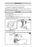
1. Disassembling the Base
(1) Place the main body with the Base
[68] <64>
positioned at the bottom.
(2) Fix Lever (A)
[58] <54>
in place.
(3) Remove Screw M8
[51] <47>
with a 13-mm wrench.
(4) Loosen Lever (A) [
58] <54>
, and then remove the Base
[68] <64>
from the main body. Because the
Springs
[41] <37>
and
[55] <51>
are contained inside the columns on the base, firmly hold the handle to
support the main body when removing the base.
2. Disassembling the Top Cover
(1) Loosen the two Tapping Screws (W/Flange) D4 x 20 (Black)
[7] <4>
, and then remove the Top Cover
[1] <1>
.
Base
[68] <64>
Screw M8
[51] <47>
Spring
[55] <51>
Disassembly
REPAIR GUIDE
Lever (A)
[58] <54>
Spring
[41] <37>
Fig. 1
Fig. 2
Tapping Screw
(W/Flange) D4 x 20
(Black)
[7] <4>
Top Cover
[1] <1>
HOUSING ASS'Y
[36] <32>


