background image

ENGLISH

NOTES

About screen defects

• High precision technology is used in the making of plasma panels but there may be dark spots (points that do not illuminate) and bright spots

(points that are too bright) in some cases. These do not indicate a malfunction.

About residual images

• In some cases, residual images may remain after the short-term display of still images and another image is displayed, but these will

disappear and return to normalcy. This is not a malfunction.

About the panel screen

• Plasma displays display images by means of electrical discharges inside the panel. Because of this, the temperature of the panel surface may

rise in some cases.Also, plasma displays are made of finely processed glass. A reinforced glass filter is installed over the panel surface but
avoid strong impact because there is still danger of glass breakage.

IMAGE RETENTION OF PLASMA DISPLAY

There are different characteristics that result in panel image retention depending on how the plasma display is used.
Situations and effective usage methods related to ghosting are provided below. 

Image retention characteristics of a plasma display

The image retention phenomenon of a plasma panel occurs due to partial phosphor degradation arising from partial character and figure
display.

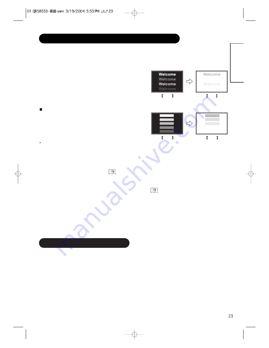
For example, when the character image as shown in Fig. A at the right is
continuously displayed for a long period of time, the only part of the phosphor
(Red,Green, Blue) that will degrade will be the color of the applicable character
display portion. Consequently, when a white image is displayed on the entire
screen as shown in Fig. a, the character marks displayed up to that time will
become a color difference visible to the eye, but the phosphor will never burn.

The degree of image retention is proportional to the brightness of the characters and figures displayed as well as the display time.

• The tendency of the phosphor is to degrade more the brighter the characters

and figures are displayed. When images of figures with different levels of
brightness, as shown in Fig. B, are continuously displayed for a long period of
time, it becomes easier for image marks at locations when the brighter figures
are displayed to be noticeable.

The image retention images in this document are exaggerated for the purpose of explanation. The actual manner in which the image retention
is seen differs depending on the operation time and brightness.

Methods to Reduce the Occurrence of Image Retention

• Lower the Contrast and Brightness settings of the plasma display as much as possible.

A function is provided in the display that controls the brightness of the screen to reduce degradation of the panel. Using this function makes it
possible to reduce image retention.
(Refer to Panel Life (Extend 1.or Extend 2 shown on           )

• Set the plasma monitor to an “Screen Wipe” or “Inverse” display.

The occurrence of image retention when displaying images of identical patterns, such as static images, for long periods of time can be
reduced by displaying a reversed color or completely white screen for about 1 ~ 2 hours after terminating the display.
(Settings can be made using Screen Wipe and Inverse of Function MENU shown on           )

• Using in combination with moving images

Since the degradation of the fluorescent material progresses comparatively uniform for moving images, the occurrence of partial image
retention can be controlled. We recommend to use in combination with moving images such as a DVD.
* Please be careful since image retention will occur if display is left in a two screen display state for a long period of time. 
* Television broadcasts include images displayed for long periods of time in which the left and right or top and bottom of the image are cut and

broadcast station name or time are displayed for a long period of time at the same portion of the screen. Image retention in these portions can
be expected to occur, so please be aware.

Fig. A

Fig. a

Fig. B

Fig. b

Summary of Contents for 42PMA300A

Page 1: ...the future Notes on lnstallation Work This product is marketed assuming that it is installed by qualifed personnel with enough skill and competence Always have an installation specialist or your dealer install and set up the product HITACHI cannot assume liabilities for damage caused by mistake in installation or mounting misuse modification or a natural disaster Note for Dealers After installatio...

Page 2: ...high definition plasma display panel The 42 inch color plasma display panel with a resolution of 852 H x 480 V pixels creates a high definition large screen aspect ratio 16 9 and low profile flat display Free from electromagnetic interferences from geomagnetic sources and ambient power lines the panel produces high quality display images free from color misconvergence and display distortion High P...

Page 3: ...tice While meticulous care has been taken in the preparation of this manual you are requested to notify your dealer or us should you have any comments views or questions about our product Fully understand the prerequisites to using the product such as hardware and software specifications and constraints in using the product We are not held liable for damages caused by improper handling of the prod...

Page 4: ... objects could result in fire or electrical shock Use special caution in households where children are present If liquids or foreign objects should enter the projector immediately turn off the power switch disconnect the power plug from the power outlet and contact your dealer Do not place the monitor in a bathroom Do not expose the monitor to rain or moisture Do not place flower vases pots cups c...

Page 5: ...ot place a spread cover etc over them because this could result in the inadvertent placing of heavy objects on the concealed power cord or cables Do not pull the power cord and cables When connecting and disconnecting the power cord or cables do it with your hand holding the plug or connector Do not place the cord near the heater Do not touch the power plug just after disconnecting it from the pow...

Page 6: ...t knock or rub the surface with sharp or hard objects Clean the screen with a soft cloth moistened with warm water and dry with a soft cloth If it is not enough then use a cloth with mild detergent Do not use harsh or abrasive cleaners How to clean the cabinet of the monitor Use a soft cloth to clean the cabinet and control panel of the monitor When excessively soiled dilute a neutral detergent in...

Page 7: ...ts on the remote control Avoid strong rays Any strong rays such as direct sun rays or room lighting onto the remote control sensors could invalidate the remote control Avoid radio interference Any interfering radiation could cause distorted images or noises Avoid radio generator such as a mobile telephone transceiver etc around the monitor Set the sound volume at a suitable level It is better to k...

Page 8: ...on INPUT SELECT button OK button RECALL button SELECT button Adjustment buttons are located on the bottom The back cover is provided with indications to distinguish the adjustment buttons SUB POWER button Control panel VOLUME UP DOWN buttons ADJUST buttons Main power switch The main power switch is located at the back on the lower surface Indicating lamp External device connection terminals Rear R...

Page 9: ...CALL MENU ID ID SET Do not use new and old batteries together The batteries could explode or leak resulting in fires physical injury or stains When loading batteries observe their correct polarities as marked on the product If loaded in the wrong direction the batteries could explode or leak resulting in fires physical injury or stains CAUTION ATTENTION Do not drop or impact the remote control Do ...

Page 10: ...k your dealer to provide the name of a qualified installer In order to prevent an internal temperature increase maintain a space of 10cm 4 inches For a desktop set up or more between the sides and other objects such as walls etc so that the ventilation holes are not blocked CAUTION Have this unit mounted in a stable place Take measures to prevent it from tumbling down to avoid possible physical in...

Page 11: ...turned off 3 Connect the signal input terminal RGB 1 or RGB 2 on the rear panel of this device to the display signal output terminal of the personal computer Use a cable that fits the input terminal of this device and the output terminal of the personal computer Depending on the type of personal computer being connected the use of an optional conversion adapter or the adapter provided with the per...

Page 12: ...ord after completing all other connections INSTALLATION INSTRUCTIONS continued Power Cord Connection Use only the power cord provided Do not use a power supply voltage other than that indicated AC100 240V 50 60Hz as this may cause fire or electric shock CAUTION Mounting the Speaker Unit option Refer to the instruction manual concerning mounting of the optional speaker unit ...

Page 13: ...emote control or the SUB POWER button on the underside of the front of the frame is ON Lights orange Off Power Save When the main power switch is ON and the ON button on the remote control or the SUB POWER button on the underside of the front of the frame is ON However the state in POWER SAVE mode When the indicating lamp lights in orange or the message No Sync Signal Power Save or Invalid Scan Fr...

Page 14: ... can be switched by pressing the RGB1 RGB2 buttons of the remote control Input can be switched in the sequence of RGB1 RGB2 by pressing the INPUT SELECT button of the monitor When a button is pressed the volume adjustment status guide will be displayed The volume will increase when the VOL or button is pressed while the guide is being displayed The volume will decrease when the VOL or button is pr...

Page 15: ...e Signal mode Input horizontal frequency Input vertical frequency The input signal status can be displayed on the screen by pressing the RECALL button of the remote control or the monitor The display will go out in approximately 6 seconds Off timer On timer RGB RECALL button Display area selection diagram RGB input Resolution Full display Circular display Display Full Normal Real Zoom1 Zoom2 Zoom3...

Page 16: ...s separate control of up to a maximum of seven monitors Remote control ID No 2 initially ID no 1 can be set by pressing the ID SET button for 2 sec or more while holding down the ID button The number will be incremented 2 6 7 1 2 when this button pressed continuously The ID remote control is operated by pressing the various buttons while holding down the ID button Operation is possible only when t...

Page 17: ...is increased in reddish color Adjust color temperature depending on the user s preference These settings are independently stored in each of the 4 Color Temperature modes Green Brighter scene is decreased in greenish color Brighter scene is increased in greenish color Blue Brighter scene is decreased in bluish color Brighter scene is increased in bluish color Cut Off Red Dark scene is decreased in...

Page 18: ...um Perfect Volume Off On This will automatically adjust volume so each channel and input has the same average volume level Reset off the function waiting to reset The original factory settings for the items of this Menu page can be restored by pressing the OK button Picture Audio Timer Function Setup Language Select OK Set Audio Audio Mode Movie Treble 10 Bass 10 Balance 0 L R SRS TruBass Middle M...

Page 19: ... Optional grayed out Reset off the function waiting to reset The original factory settings for the items of this Menu page can be restored by pressing the OK button Panel Life Normal Extend 1 Extend 2 This function is to suppress the contrast of the screen regardless of the Contrast setting in the Picture Menu By this control power consumption can be reduced or degradation of a panel can be mitiga...

Page 20: ...Vertical Filter On Frequency Mode Movie RGB1 DVI PC RGB2 RGB Select Set Return OK MENU OPERATING INSTRUCTIONS continued Depending on the type of signal displayed displays may not be optimized through automatic adjustment Adjust manually to optimize them OK Horizontal Position 0 Next Prev Adjust Return Setup Auto Adjust Adjust Horizontal Position 0 Vertical Position 31 Horizontal Clock 20 Clock Pha...

Page 21: ... Tint Picture Enhancement Color temperature Color Temp Adjust R Amplitude For every Color Temperature 1 setting is registered G Amplitude B Amplitude R Cut Off G Cut Off B Cut Off Audio Audio Mode 1 setting is registered Treble For every Audio Mode 1 setting is registered Bass Balance 1 setting is registered SRS TruBass For every Audio Mode 1 setting is registered Matrix Surround Perfect Volume Me...

Page 22: ...Recheck the input signal specifications No Sync Signal Changes in the signal status are displayed on the screen as they arise OTHER FEATURES continued RGB2 RGB H 48 4kHz V 60 1 Hz Min OFF RGB Invalid Scan Freq Power Save Mode When the RGB1 RGB2 input is selected When this unit is connected to a VESA DPMS computer the Power Save Off mode can be set to be activated automatically when the computer is...

Page 23: ...ay time The tendency of the phosphor is to degrade more the brighter the characters and figures are displayed When images of figures with different levels of brightness as shown in Fig B are continuously displayed for a long period of time it becomes easier for image marks at locations when the brighter figures are displayed to be noticeable The image retention images in this document are exaggera...

Page 24: ...Scan Freq is displayed Invalid Scan Freq An input signal is not received normally Check to see if the input signal matches the monitor specifications Check the way the signal cable is connected The power indicating lamp is normally lit but no picture Check the contrast and brightness settings adjust them for higher contrast and brightness Check the way the signal cable is connected The display ima...

Page 25: ...ENGLISH ...

Page 26: ...Clock adjustment 6 Press the or ADJUST buttons and search for clear characters over the entire screen 7 Perform adjustment for symptom 2 below when the characters are blurred on the entire screen The display image may be momentarily disturbed during clock adjustment but this is not a failure Symptom 2 Text displayed across the screen appears blurred in its entirety figure 2 A fine pattern flickers...

Page 27: ... excluding Speakers Stand 830 W x 506 H x 92 D mm 1030 W x 636 H x 91 D mm Net weight excluding Speakers Stand 24 6kg 34 9kg Ambient conditions Temperature Operating 5 C to 35 C Storage 0 C to 40 C Relative humidity Operating 20 to 80 Storage 20 to 90 non condensing Power supply AC100 240V 50 60Hz Power consumption at standby 255W 3W 365W 3W Audio output 12W 12W 6Ω RGB input Input signals Input te...

Page 28: ...V 3 T M D S Data2 4 Shield 16 Hot Plug Detect 4 T M D S Data4 17 T M D S Data0 5 T M D S Data4 18 T M D S Data0 6 DDC Clock 19 T M D S Data0 5 Shield 7 DDC Data 20 T M D S Data5 8 No Connect 21 T M D S Data5 9 T M D S Data1 22 T M D S Clock Shield 10 T M D S Data1 23 T M D S Clock 11 T M D S Data1 3 Shield 24 T M D S Clock 12 T M D S Data3 Frame GND 13 T M D S Data3 With Digital RGB signal input R...

Page 29: ...frequency of 85Hz or higher is input to it The monitor differentiates the signal modes according to the horizontal and vertical frequencies and the horizontal and vertical sync signal polarities Note that different signals having all these elements alike may be handled as the same signal Displaying images with more than 480 lines of vertical resolution at Full diplay compressed display can result ...

Page 30: ...SUPPLEMENT ...

Page 31: ...Connecting to a Video Imaging Device If video equipment with an S video output terminal is used cabling by the S video cable is recommended to provide finer video quality If an S video input terminal and a video input terminal of AV3 connect to the monitor at the same time S video input would govern If the OUTPUT MONITOR terminal is connected to an external monitor with a 75 Ohm terminal it is pos...

Page 32: ...20p 60 4 3 Panoramic Zoom Full Cinema Display size selection diagram When you want to Set the display size to Input signal Display screen Remarks Play a 4 3 image in a 16 9 screen faithfully 4 3 Blanking occurs on both sides Play a 4 3 image in a 16 9 screen with the height and width of the middle of the screen enlarged on equal scales and with both sides appearing somewhat enlarged Panoramic Play...

Page 33: ... normal 4 3 image is displayed over the entire screen in the Panoramic mode parts of the periphery of the image may disappear and or appear distorted in some cases Use the 4 3 mode to view images which were created in 4 3 mode This mode allows 4 3 content to be viewed without picture distortion Press Vertical picture position can be adjusted for Panoramic Zoom and Cinema mode as follows 1 Press SI...

Page 34: ...uttons the audio of the video will be output from the side on which the speaker icon is located The same video input mode cannot be selected for both screens at the same time Pressing the PinP button again or the RETURN button will cancel the 2 pictures display When the Video input is set to RGB Video this Split mode is not possible Refer to the table for 2 pictures Split mode PinP button RETURN b...

Page 35: ...namic Color Temp Adjust Color Management Color Decoding Select Set Return OK Picture Dynamic Color Temp Adjust Color Management Color Decoding Select Set Return OK Picture Color Management On Magenta 60 Red 30 Yellow 0 Green 60 Cyan 30 Blue 0 Reset Reset Select On Off Return OK OK PICTURE MENU OK OK Picture Mode Dynamic Next Prev Select Return YNR Off Next Prev Select Return Picture Dynamic YNR Of...

Page 36: ...s for the items of this Menu page can be restored by pressing the OK button YNR Off Low High Performs picture signal noise reduction Turn up to reduce noise CNR Performs color signal noise reduction Turn up to reduce noise And it will be fixed as Off only when selecting DVI STB mode Film Mode Off On On Automatically detects the movie film material and faithfully reproduces the original film image ...

Page 37: ...ime the setting is changed Red Darkens red only Lightens red only This adjusts R G B level or tint to make the color appear natural for the user s preference These settings are independently stored in each of the 4 Color Temperature modes Green Darkens green only Lightens green only Color Darkens colors Lightens colors Tint Enhances red and weakens green Enhances green and weakens red FUNCTION MEN...

Page 38: ...mally set this to Auto The system of the input signal will be automatically recognized If the input signal contains much noise or has a low level at Auto and the operation is found erratic set this to match the input signal When the component signal is received this would be not available grayed out AV2 Same to AV1 AV3 AV4 Video Input AV1 Auto HDTV SDTV DVD This should correspond to the signal mod...

Page 39: ...ting is registered Color System 1 setting is registered AV1 AV2 AV3 AV4 Video Input AV1 1 setting is registered AV2 AV4 Audio Input AV1 1 setting is registered AV2 AV3 AV4 RGB1 RGB2 The previously recorded items will be lost Selected characters Setup hint Audio Input AV1 Stereo L Mono This should correspond to the audio signal from the equipment that is connected to AV1 audio input terminal If it ...

Page 40: ...supply AC100 240V 50 60Hz Power consumption at standby 255W 3W 365W 3W Audio output 12W 12W 6Ω RGB input Input signals Input terminals RGB1 DVI input terminal DVI D RGB1 audio input terminal 3 5mm Stereo Mini Jack RGB2 analog RGB input terminal D sub 15 pin RGB2 audio input terminal 3 5mm Stereo Mini Jack Video signals 0 7 V 1 0 Vp p analog RGB Recommended Signal 480i 576i 480p 576p 1080i 50 1080i...

Page 41: ...IN RGB terminal D sub 15 pin connector 1 2 3 4 5 6 7 8 9 10 11 12 13 14 15 When different kinds of input signals are simultaneously input to the monitor via a graphics board or the like the monitor will automatically select the signals in the following priority order Even in the case of the recommended signals shown on the following page there may be instances when correct display is not possible ...

Page 42: ...nd AV4 input No Signal mode Horizontal frequency kHz Dot clock frequency MHz Remarks Signal Name Resolution Vertical frequency Hz 1 576i 576 50 00 15 63 2 480i 480 59 94 15 73 3 576p 576 50 00 31 26 4 480p 480 59 94 31 47 5 1080i 50 1080 50 00 28 13 6 1080i 60 1080 60 00 33 75 7 720p 60 720 59 94 44 96 With component input AV1 AV2 and RGB2 component input The monitor differentiates the signal mode...

Reviews: