background image

12

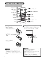
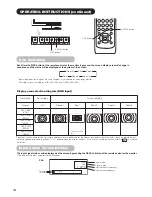
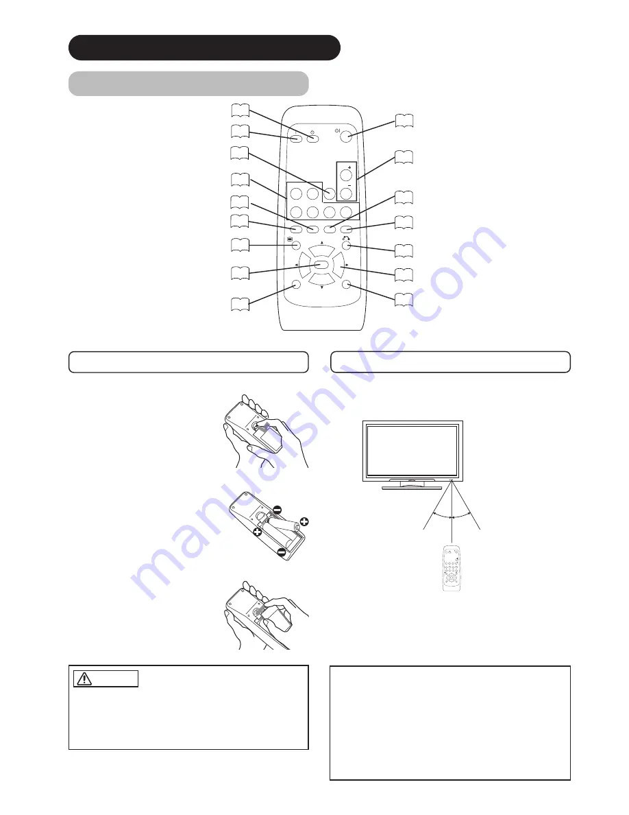
Remote control

ID SET button

19

POWER OFF button

16

POWER ON button

16

POWER ON/OFF button

16

MENU button

19

MUTE button

17

VOLUME UP/DOWN buttons

17

RETURN button

19

RECALL button

18

AUTO button

19

PinP button

37

ID button

19

SELECT/ADJUST buttons

19

OK button

19

Loading Batteries

1. Open the battery cover.

• Slide back and remove the battery

cover in the direction of the arrow.

2. Load batteries.

• Load two Size AA batteries included observing the correct

polarities.

3. Close the battery cover.

• Replace the battery cover in the direction of the arrow and snap

it back into place.

Use the remote control within about 5 m from front of the unit’s
remote-control sensor and within 30 degrees on both sides.

With in 30
degrees

About 5m

About 3m

With in 30
degrees

About 3m

AV1

AV2

RGB 1

RGB 2

AV3

MUTE

VOL

VOL

AV4

AUTO

PinP

OK

SIZE

RECALL

    MENU

ID

ID SET

• Do not use new and old batteries together.  The batteries could

explode or leak, resulting in fires, physical injury, or stains.

• When loading batteries, observe their correct polarities as

marked on the product. If loaded in the wrong direction, the
batteries could explode or leak, resulting in fires, physical injury,
or stains.

CAUTION

ATTENTION 

• Do not drop or impact the remote control.
• Do not splash the remote control with water or put it on a wet

object to avoid possible failures.

• Before leaving the remote control out of use for an extended

period of time, remove the batteries from it.

• If the remote control begins to lack responsiveness, replace the

batteries.

• Strong light such as direct sunlight impinging on the

photoreceptor of the remote control can cause operational failure.
Position this unit to avoid direct contact with such light.

Handling the Remote Control

COMPONENT NAMES (continued)

SIZE button

18

RGB/VIDEO buttons

17

AV1

AV2

RGB 1

RGB 2

AV3

MUTE

VOL

VOL

AV4

AUTO

PinP

OK

SIZE

RECALL

    MENU

ID

ID SET

Summary of Contents for 42HDM70

Page 1: ... NO The serial number is located on the rear of the monitor This monitor is ENERGY STAR compliant when used with a computer equipped with VESA DPMS The ENERGY STAR emblem does not represent EPA endorsement of any product or service As an ENERGY STAR Partner Hitachi Ltd has determined that this product meets the ENERGY STAR guidelines for energy efficiency Color Plasma Display Monitor Model PW1 42H...

Page 2: ... the future Notes on lnstallation Work This product is marketed assuming that it is installed by qualifed personnel with enough skill and competence Always have an installation specialist or your dealer install and set up the product HITACHI cannot assume liabilities for damage caused by mistake in installation or mounting misuse modification or a natural disaster Note for Dealers After installati...

Page 3: ...operating and maintenance servicing instructions in the literature accompanying the appliance WARNING TO PREVENT FIRE OR SHOCK HAZARD DO NOT EXPOSE THIS MONITOR TO RAIN OR MOISTURE THE MONITOR SHOULD NOT BE EXPOSED TO DRIPPING OR SPLASHING AND NO OBJECTS FILLED WITH LIQUIDS SUCH AS VASES SHOULD NOT BE PLACED ON THE MONITOR NOTE There are no user serviceable parts inside the monitor Model and seria...

Page 4: ...sonal injury 16 Follow instructions for wall shelf or ceiling mounting as recommended by the manufacturer 17 An outdoor antenna should not be located in the vicinity of overhead power lines or other electrical circuits 18 If an outside antenna is connected to the receiver be sure the antenna system is grounded so as to provide some protection against voltage surges and built up static charges Sect...

Page 5: ...r cracks Large screen high definition plasma display panel The 42 inch color plasma display panel with a resolution of 1024 H x 1024 V pixels creates a high definition large screen aspect ratio 16 9 and low profile flat display Free from electromagnetic interferences from geomagnetic sources and ambient power lines the panel produces high quality display images free from color misconvergence and d...

Page 6: ...to change without notice While meticulous care has been taken in the preparation of this manual you are requested to notify your dealer or us should you have any comments views or questions about our product Fully understand the prerequisites to using the product such as hardware and software specifications and constraints in using the product We are not held liable for damages caused by improper ...

Page 7: ...n objects could result in fire or electrical shock Use special caution in households where children are present If liquids or foreign objects should enter the projector immediately turn off the power switch disconnect the power plug from the power outlet and contact your dealer Do not place the monitor in a bathroom Do not expose the monitor to rain or moisture Do not place flower vases pots cups ...

Page 8: ...cables Also do not place a spread cover etc over them because this could result in the inadvertent placing of heavy objects on the concealed power cord or cables Do not pull the power cord and cables When connecting and disconnecting the power cord or cables do it with your hand holding the plug or connector Do not place the cord near the heater Do not touch the power plug just after disconnecting...

Page 9: ...ot knock or rub the surface with sharp or hard objects Clean the screen with a soft cloth moistened with warm water and dry with a soft cloth If it is not enough then use a cloth with mild detergent Do not use harsh or abrasive cleaners How to clean the cabinet of the monitor Use a soft cloth to clean the cabinet and control panel of the monitor When excessively soiled dilute a neutral detergent i...

Page 10: ...lace heavy objects on the remote control Avoid strong rays Any strong rays such as direct sun rays or room lighting onto the remote control sensors could invalidate the remote control Avoid radio interference Any interfering radiation could cause distorted images or noises Avoid radio generator such as a mobile telephone transceiver etc around the monitor Set the sound volume at a suitable level I...

Page 11: ...n regulations provided that following conditions are met Video inputs The input signal amplitude must not exceed the specified level CAUTION Changes or modifications not expressly approved by the party responsible for compliance could void the user s authority to operate the equipment Declaration of Conformity According to 47CFR Part 2 and 15 for Class B Personal Computers and Peripherals and or C...

Page 12: ...T SELECT button OK button 17 RECALL button SELECT button 18 Adjustment buttons are located on the bottom The back cover is provided with indications to distinguish the adjustment buttons SUB POWER button 16 Control panel VOLUME UP DOWN buttons ADJUST buttons 17 Main power switch 16 16 The main power switch is located at the back on the lower surface Indicating lamp External device connection termi...

Page 13: ... RECALL MENU ID ID SET Do not use new and old batteries together The batteries could explode or leak resulting in fires physical injury or stains When loading batteries observe their correct polarities as marked on the product If loaded in the wrong direction the batteries could explode or leak resulting in fires physical injury or stains CAUTION ATTENTION Do not drop or impact the remote control ...

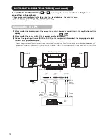
Page 14: ...lf Ask your dealer to provide the name of a qualified installer In order to prevent an internal temperature increase maintain a space of 10cm 4 inches For a desktop set up or more between the sides and other objects such as walls etc so that the ventilation holes are not blocked CAUTION Have this unit mounted in a stable place Take measures to prevent it from tumbling down to avoid possible physic...

Page 15: ...al computer is turned off 3 Connect the signal input terminal RGB 1 or RGB 2 on the rear panel of this device to the display signal output terminal of the personal computer Use a cable that fits the input terminal of this device and the output terminal of the personal computer Depending on the type of personal computer being connected the use of an optional conversion adapter or the adapter provid...

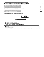
Page 16: ...wer cord after completing all other connections INSTALLATION INSTRUCTIONS continued Power Cord Connection Use only the power cord provided Do not use a power supply voltage other than that indicated AC100 240V 50 60Hz as this may cause fire or electric shock CAUTION Mounting the Speaker Unit option Refer to the instruction manual concerning mounting of the optional speaker unit ...

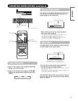
Page 17: ...control or the SUB POWER button on the underside of the front of the frame is ON Lights orange Off Power Save When the main power switch is ON and the ON button on the remote control or the SUB POWER button on the underside of the front of the frame is ON However the state in POWER SAVE mode When the indicating lamp lights in orange or the message No Sync Signal Power Save or Invalid Scan Freq app...

Page 18: ...Input can be switched by pressing the RGB1 RGB2 buttons of the remote control Input can be switched in the sequence of RGB1 RGB2 by pressing the INPUT SELECT button of the monitor When a button is pressed the volume adjustment status guide will be displayed The volume will increase when the VOL or button is pressed while the guide is being displayed The volume will decrease when the VOL or button ...

Page 19: ...orizontal frequency Input vertical frequency The input signal status can be displayed on the screen by pressing the RECALL button of the remote control or the monitor The display will go out in approximately 6 seconds Off timer On timer RGB OPERATING INSTRUCTIONS continued RECALL button Display area selection diagram RGB input Resolution Full display Circular display Display Full Normal Real Zoom1...

Page 20: ...ws separate control of up to a maximum of seven monitors Remote control ID No 2 initially ID no 1 can be set by pressing the ID SET button for 2 sec or more while holding down the ID button The number will be incremented 2 6 7 1 2 when this button pressed continuously The ID remote control is operated by pressing the various buttons while holding down the ID button Operation is possible only when ...

Page 21: ...ng is adjusted Brightness Black is subdued for increased overall darkness Black is set off for increased overall brightness Adjust to taste Color Darkens colors Lightens colors Adjust to taste Tint Enhances red and weakens green Enhances green and weakens red This is not available to adjust when receiving PAL SECAM signal In this case the character will be grayed out Adjust for most realistic skin...

Page 22: ... stadium Perfect Volume Off On This will automatically adjust volume so each channel and input has the same average volume level Reset off the function waiting to reset The original factory settings for the items of this Menu page can be restored by pressing the OK button Picture Audio Timer Function Setup Language Select OK Set Audio Audio Mode Movie Treble 10 Bass 10 Balance 0 L R SRS TruBass Mi...

Page 23: ...t Reset off the function waiting to reset The original factory settings for the items of this Menu page can be restored by pressing the OK button Panel Life Normal Extend 1 Extend 2 This function is to suppress the contrast of the screen regardless of the Contrast setting in the Picture Menu By this control power consumption can be reduced or degradation of a panel can be mitigated The order of po...

Page 24: ...ored by pressing the OK button This is effective only for RGB2 Input Level 0 7V 1 0V Normally set to 0 7 V If white is found to spread across the screen set to 1 0 V This is effective only for RGB2 Frequency Display Off On Set this to Off if the frequency information of the Input Signal Screen Display is not required WVGA Type Off On This is only available for W VGA signal When it is set to On the...

Page 25: ... Audio Mode 1 setting is registered Bass Balance 1 setting is registered SRS TruBass For every Audio Mode 1 setting is registered Matrix Surround Perfect Volume Menu Display Registration condition Function Screen Saver 1 setting is registered Screen Wipe not registered Black Side Panel not registered Panel Life 1 setting is registered Mode Display ID Number Inverse Standby White Gamma Setup Auto A...

Page 26: ...q Recheck the input signal specifications 30 32 No Sync Signal Changes in the signal status are displayed on the screen as they arise OTHER FEATURES continued RGB2 RGB H 48 4kHz V 60 1 Hz Min OFF RGB Invalid Scan Freq Power Save Mode When the RGB1 RGB2 input is selected When this unit is connected to a VESA DPMS computer the Power Save Off mode can be set to be activated automatically when the com...

Page 27: ...me The tendency of the phosphor is to degrade more the brighter the characters and figures are displayed When images of figures with different levels of brightness as shown in Fig B are continuously displayed for a long period of time it becomes easier for image marks at locations when the brighter figures are displayed to be noticeable The image retention images in this document are exaggerated f...

Page 28: ...isplayed Invalid Scan Freq An input signal is not received normally Check to see if the input signal matches the monitor specifications Check the way the signal cable is connected The power indicating lamp is normally lit but no picture Check the contrast and brightness settings adjust them for higher contrast and brightness Check the way the signal cable is connected The display image appears flo...

Page 29: ...cause vertical stripes to appear because of failure to light Please note that this is not a malfunction Coarse horizontal stripes appear in FULL display Adjusting the Clock Phase will reduce the horizontal stripes RGB input Flickering in the form of horizontal lines oscillating up and down PC INPUT MODE only If the direct frequency from the computer is below 85Hz try a higher frequency upper limit...

Page 30: ...ntal Clock adjustment 6 Press the or ADJUST buttons and search for clear characters over the entire screen 7 Perform adjustment for symptom 2 below when the characters are blurred on the entire screen The display image may be momentarily disturbed during clock adjustment but this is not a failure Symptom 2 Text displayed across the screen appears blurred in its entirety figure 2 A fine pattern fli...

Page 31: ...tand 1030 W x 636 H x 91 D mm Net weight excluding Speakers Stand 34 9kg Ambient conditions Temperature Operating 5 C to 35 C Storage 0 C to 40 C Relative humidity Operating 20 to 80 Storage 20 to 90 non condensing Power supply AC100 240V 50 60Hz Power consumption at standby 365W 3W Audio output 12W 12W 6Ω RGB input Input signals Input terminals RGB1 DVI input terminal DVI D RGB1 audio input termi...

Page 32: ...13 T M D S Data3 With Digital RGB signal input RGB1 input No Signal mode Horizontal frequency kHz Dot clock frequency MHz Remarks Signal Name Resolution Vertical frequency Hz 1 VGA 640 X 400 70 08 31 47 25 18 2 640 X 480 59 94 31 47 25 18 3 W VGA 864 X 480 60 00 31 02 33 75 4 864 X 480 59 94 31 47 34 24 WVGA type On 5 VESA 640 X 480 72 81 37 86 31 50 6 640 X 480 75 00 37 50 31 50 7 640 X 480 85 01...

Page 33: ...Remarks Signal Name Resolution Vertical frequency Hz 1 VGA 640 X 400 70 08 31 47 25 18 2 640 X 480 59 94 31 47 25 18 3 W VGA 864 X 480 59 94 31 47 34 24 WVGA type On 4 VESA 640 X 480 72 81 37 86 31 50 5 640 X 480 75 00 37 50 31 50 6 640 X 480 85 01 43 27 36 00 7 800 X 600 56 25 35 16 36 00 8 800 X 600 60 32 37 88 40 00 9 800 X 600 72 19 48 08 50 00 10 800 X 600 75 00 46 88 49 50 11 800 X 600 85 06...

Page 34: ...33 ENGLISH SUPPLEMENT ...

Page 35: ... AV4 input that is displayed on the screen at the time If the adaptor is applied to AV4 input as shown in the drawing it is impossible to receive RGB signal With DVI STB and RGB component setup To component video equipments Please use the connection cable suitable for the terminal form of video equipment 34 45 Applicable video signals for each input terminal See PRODUCT SPECIFICATIONS for details ...

Page 36: ...60 or 720p 60 4 3 Panoramic Zoom Full Cinema Display size selection diagram When you want to Set the display size Input signal Display screen Remarks Play a 4 3 image in a 16 9 screen faithfully 4 3 Blanking occurs on both sides Play a 4 3 image in a 16 9 screen with the height and width of the middle of the screen enlarged on equal scales and with both sides appearing somewhat enlarged Panoramic ...

Page 37: ...ormal 4 3 image is displayed over the entire screen in the Panoramic mode parts of the periphery of the image may disappear and or appear distorted in some cases Use the 4 3 mode to view images which were created in 4 3 mode This mode allows 4 3 content to be viewed without picture distortion Press Vertical picture position can be adjusted for Panoramic Zoom and Cinema mode as follows 1 Press SIZE...

Page 38: ... SELECT buttons the audio of the video will be output from the side on which the speaker icon is located The same video input mode cannot be selected for both screens at the same time Pressing the PinP button again or the RETURN button will cancel the 2 pictures display When the Video input is set to RGB Video this Split mode is not possible Refer to the table for 2 pictures Split mode PinP button...

Page 39: ...coding Select Set Return OK Picture Day Color Temp Adjust Color Management Color Decoding Select Set Return OK Picture Color Management On Magenta 60 Red 30 Yellow 0 Green 60 Cyan 30 Blue 0 Reset Reset Select On Off Return OK OK Picture Color Decoding RGB R G B Red 0 Green 60 Color 0 Tint 31 Reset Reset Select Return Exit OPERATING INSTRUCTIONS continued PICTURE MENU Picture Mode Day Next Prev Sel...

Page 40: ...s for the items of this Menu page can be restored by pressing the OK button YNR Off Low High Performs picture signal noise reduction Turn up to reduce noise CNR Performs color signal noise reduction Turn up to reduce noise And it will be fixed as Off only when selecting DVI STB mode Film Mode Off On On Automatically detects the movie film material and faithfully reproduces the original film image ...

Page 41: ...ss the OK button every time the setting is changed Red Darkens red only Lightens red only This adjusts R G B level or tint to make the color appear natural for the user s preference These settings are independently stored in each of the 4 Color Temperature modes Green Darkens green only Lightens green only Color Darkens colors Lightens colors Tint Enhances red and weakens green Enhances green and ...

Page 42: ...Normally set this to Auto The system of the input signal will be automatically recognized If the input signal contains much noise or has a low level at Auto and the operation is found erratic set this to match the input signal When the component signal is received this would be not available grayed out AV2 Same to AV1 AV3 AV4 Video Input AV1 Auto HDTV SDTV DVD This should correspond to the signal ...

Page 43: ...ut signal Approximately 1 sec after adjustment is completed the adjustments will be recorded as shown in the table below OTHER FEATURES Automatic Store Menu Display Registration condition Picture Picture Mode 1 setting is registered Contrast For every input function and every Picture Mode 1 setting is registered Brightness Color Sharpness Tint Color Temperature Contrast Mode YNR CNR Film Mode PAL ...

Page 44: ...wer consumption at standby 365W 3W Audio output 12W 12W 6Ω RGB input Input signals Input terminals RGB1 DVI input terminal DVI D RGB1 audio input terminal 3 5mm Stereo Mini Jack RGB2 analog RGB input terminal D sub 15 pin RGB2 audio input terminal 3 5mm Stereo Mini Jack Video signals 0 7 V 1 0 Vp p analog RGB Recommended Signal 480i 576i 480p 576p 1080i 50 1080i 60 720p 60 Sync signals H V separat...

Page 45: ...SSIS 11 RGB G IN RGB terminal D sub 15 pin connector 1 2 3 4 5 6 7 8 9 10 11 12 13 14 15 When different kinds of input signals are simultaneously input to the monitor via a graphics board or the like the monitor will automatically select the signals in the following priority order Even in the case of the recommended signals shown on the following page there may be instances when correct display is...

Page 46: ...z Dot clock frequency MHz Remarks Signal Name Resolution Vertical frequency Hz 1 NTSC M PAL M 525 59 94 15 73 2 PAL N 625 50 00 15 63 With Composite Input AV1 AV4 input and S video Input AV3 input No Signal mode Horizontal frequency kHz Dot clock frequency MHz Remarks Signal Name Resolution Vertical frequency Hz 1 NTSC M PAL M PAL N 525 625 59 94 50 00 15 73 15 63 With R G B Video input AV2 and AV...

Page 47: ... apparaître dans ce manuel MARQUES DÉPOSÉES VGA et XGA sont des marques déposées d International Business Machines Corporation APPEL et Macintosh sont des marques déposées d Apple Computer Inc VESA est une marque déposée d une organisation sans but lucratif La Video Electronics Standard Association Toutes les marques ou noms de produit sont des marques de commerce ou des marques déposées de leur d...

Page 48: ...erica LTD Home Electronics Division 900 Hitachi Way Chula Vista CA 91914 U S A Tel 1 800 HITACHI 1 800 448 2244 Hitachi Canada LTD Digital Media Division 6740 Campobello Road Mississauga ON L5N 2L8 CANADA Tel 1 800 HITACHI 1 800 448 2244 ...

Reviews: