background image

PAL B, G, H / I / D, K
SECAM B, G / D, K / K1
NTSC-M

OUTPUT (MONITOR): composite video monitor-output terminal (RCA)
OUTPUT (MONITOR): L/R audio monitor- output terminal (RCA)
OUTPUT (HEADPHONE): L/R audio monitor- output terminal (Mini-pin)

AV1: composite video input terminal (RCA)
AV1: Y PB PR video input terminal (RCA)
AV1: L/R audio input terminal (RCA)
AV2: composite video input terminal (RCA)
AV2: Y/ P

/ P

/ video input terminal (RCA)

AV2: L/R audio input terminal (RCA)
AV3: composite video input terminal (RCA)
AV3: S video input terminal
AV3: L/R audio input terminal (RCA)
AV4: composite video / L/R audio input terminal (RCA)
AV5=AV3
AV6=HDMI input terminal
Photo input terminal (37/42 only)

53

ENGLISH

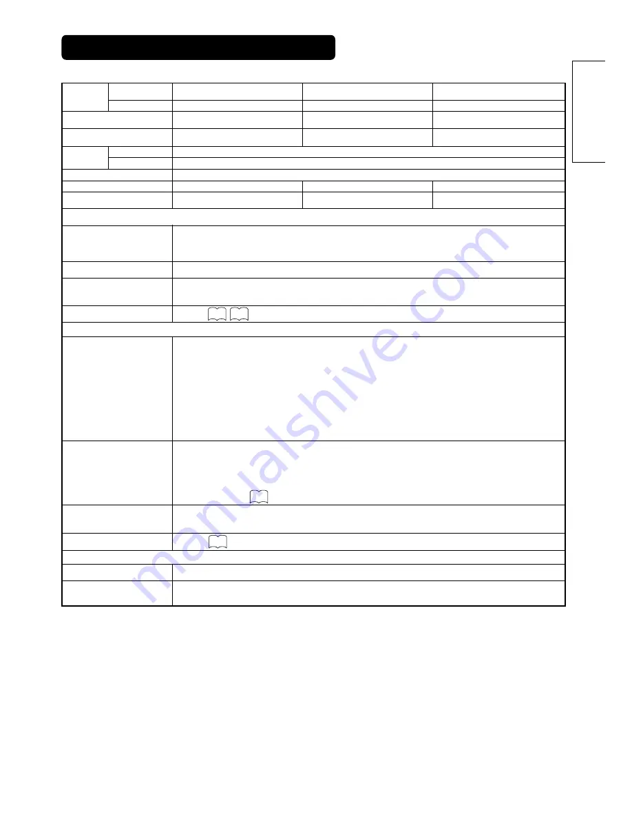
Panel

PRODUCT SPECIFICATIONS

This table shows the specifications when the optional video unit and tuner unit have been inserted.

• The monitor takes at least 30 minutes to attain the status of optimal picture quality.
• RF input : TV only

Ambient
conditions

Power supply

Power consumption/at standby

Audio output

(RGB input)

Input terminals

Input terminals

Input terminals

RF Video System

Input signals

Input signals

Sync signals

Recommended signal

Recommended signal

(RF input)

(Video input)

Output Signal

Temperature

Relative humidity

Net dimensions
(excluding Speakers/Stand)

Net weight
(excluding Speakers/Stand)

Resolution

Display 
dimensions

Approx. 32 inches (716 (H) x 399 (V) mm,
diagonal 820mm)
852 (H) x 1024 (V) pixels

850 (W) x 545 (H) x 110 (D) mm

25.5kg

Operating : 5˚C to 35˚C, Storage : 0˚C to 40˚C

Operating : 20% to 80%, Storage : 20% to 90% (non-condensing)

AC100 - 240V, 50/60Hz

245W / <3W

speaker 12W + 12W (6

)

RGB1 DVI input terminal (DVI-D)
RGB1 audio input terminal (3.5mm Stereo Mini Jack)
RGB2 analog RGB input terminal (D-sub 15-pin)
RGB2 audio input terminal (3.5mm Stereo Mini Jack)

0.7 V/1.0 Vp-p, analog RGB (Recommended Signal)
480i, 576i, 480p, 576p, 1080i/50, 1080i/60, 720p/60

H/V separate, TTL level [2K

]

H/V composite, TTL level [2K

]

Sync on green, 0.3 Vp-p [75

]

44 modes 

23 modes

ANT : 75

Unbalanced

AV1: PAL, SECAM, NTSC3.58, NTSC4.43
AV1: 480i, 576i, 480p, 576p, 1080i/50, 1080i/60, 720p/60
AV2: PAL, SECAM, NTSC4.43, NTSC3.58 
AV2: 480i, 576i, 480p, 576p, 1080i/50, 1080i/60, 720p/60, RGB
AV3: PAL, SECAM, NTSC4.43, NTSC3.58,
AV4: PAL, SECAM,  NTSC4.43, NTSC3.58,
AV5=AV3
AV6=HDMI input signal

speaker 12W + 12W (6

)

speaker 12W + 12W (6

), 

320W / <3W

380W / <3W

30.5kg

37.0kg

959 (W) x 612 (H) x 118 (D) mm

1050 (W) x 676 (H) x 110 (D) mm

1024 (H) x 1024 (V) pixels

1024(H) x 1024 (V) pixels

Approx. 37 inches (814 (H) x 445 (V) mm,
diagonal 930mm)

Approx. 42 inches (922 (H) x 522 (V) mm,
diagonal 1059mm)

56

57

55

55

Summary of Contents for 32PD7800

Page 1: ... future Notes on lnstallation Work This product is marketed assuming that it is installed by qualifed personnel with enough skill and competence Always have an installation specialist or your dealer install and set up the product HITACHI cannot assume liabilities for damage caused by mistake in installation or mounting misuse modification or a natural disaster Note for Dealers After installation b...

Page 2: ...plasma display panel with a resolution of 1024 H x 1024 V pixels the 37 inch color plasma display panel with a resolution of 1024 H x 1024 V pixels and the 32 inch color plasma display panel with a resolution of 852 H X 1024 V pixels creates a high definition large screen aspect ratio 16 9 and low profile flat display Free from electromagnetic interferences from geomagnetic sources and ambient pow...

Page 3: ... mode 43 AUDIO MENU 44 TIMER MENU 45 LANGUAGE MENU 45 Notes about This Manual The information in this manual is subject to change without notice While meticulous care has been taken in the preparation of this manual you are requested to notify your dealer or us should you have any comments views or questions about our product Fully understand the prerequisites to using the product such as hardware...

Page 4: ...or foreign objects could result in fire or electrical shock Use special caution in households where children are present If liquids or foreign objects should enter the monitor immediately turn off the power switch disconnect the power plug from the power outlet and contact your dealer Do not place the monitor in a bathroom Do not expose the monitor to rain or moisture Do not place flower vases pot...

Page 5: ...ver etc over them because this could result in the inadvertent placing of heavy objects on the concealed power cord or cables Do not pull the power cord and cables When connecting and disconnecting the power cord or cables do it with your hand holding the plug or connector Do not place the cord near the heater Do not touch the power plug just after disconnecting it from the power outlet to prevent...

Page 6: ...ce near fire A wet place such as bathroom or shower room Place where you can trip over it Always vibrating or strongly vibrating places Distorted or unstable places How to view the monitor If you use the monitor in too dark a room your eyes may become tired Please use it in a reasonably bright room Avoid direct rays of the sun to the screen in order to prevent eye fatigue Your eyes will get fatigu...

Page 7: ...id strong rays Any strong rays such as direct sun rays or room lighting onto the remote control sensors could invalidate the remote control Avoid radio interference Any interfering radiation could cause distorted images or noises Avoid radio generator such as a mobile telephone transceiver etc around the monitor Set the sound volume at a suitable level It is better to keep the volume level low and...

Page 8: ...laying images of identical patterns such as static images for long periods of time can be reduced by displaying a completely white screen for about 1 2 hours after terminating the display Luminance Manager function works to reduce image retention when displaying images on the four corners such as TV station logos and clock display Settings can be made using Screen Wipe and Luminance Manager from F...

Page 9: ...trol receiver 10 Indicating lamp The main power switch is located at the back on the lower surface Main power switch 21 21 Caution when moving the main unit As this product is heavy whenever it is moved two people are required to transport it safely Whenever the unit is moved it should be lifted forwards using the two handgrips at the back and the unit should then be held at the base on both sides...

Page 10: ... 30 degrees About 5m About 3m With in 30 degrees About 3m Do not use new and old batteries together The batteries could explode or leak resulting in fires physical injury or stains When loading batteries observe their correct polarities as marked on the product If loaded in the wrong direction the batteries could explode or leak resulting in fires physical injury or stains CAUTION ATTENTION Do not...

Page 11: ... button to change the picture to freeze mode Press it again to return to normal picture ZOOM Press this button can change Picture size RECALL TV With this button the display change between and AV00 on the top right hand corner of the screen is for 2 digit channel selection is for 3 digit channel selection and is for 1 digit channel selection RECALL Video RGB Press this button to display input sign...

Page 12: ...mporarily while searching for a required text page When the required text page has been received the page number will be displayed at the top left of the screen Press the CANCEL button again to display the TELETEXT screen Each of these buttons selects a link page displayed at the lower part of the screen This allows hidden information found on some teletext pages to be displayed on the screen Thes...

Page 13: ...n to avoid possible physical injury CAUTION Loosen a cord or chain enough while operating power swivel to avoid possible physical injury CAUTION 10cm or more Cord or chain Clamp Wall or Pillar Anti tumble measures Securing to a wall or pillar Using a commercially available cord chain and clamp secure the set to a firm wall or pillar Securing desktop 1 Using wood screws two fasten the set to the cl...

Page 14: ... input would govern If a video equipment with an S video output terminal is used cabling by the S video cable is recommended to provide finer video quality If an S video input terminal and a video input terminal of AV3 or AV5 side input connect to the monitor at the same time S video input would govern If the OUTPUT Monitor terminal is connected to an external monitor with a 75 Ohm terminal it is ...

Page 15: ...Avoid using a parallel flat feeder wire as interference may occur causing reception to be unstable and stripe noise to appear on the screen Avoid using indoor antenna as this may be affected by interference Please use CATV net or outdoor antenna Keep the power cord as far away from the antenna wire as possible For safety install an external antenna conforming to AS1417 1 applicable for Australia o...

Page 16: ...computer being connected the use of an optional conversion adapter or the adapter provided with the personal computer may be necessary in some cases For details refer to the instruction manual of the personal computer or ask the personal computer manufacturer or your local retail dealer 53 57 D sub DVI Monitor rear panel Speaker R Speaker L Power cable connector Power cord To signal output termina...

Page 17: ...systems 3 Attach the speaker connecting cables to the monitor Make sure the ferrite core is toward the monitor side Right Side Rear of the monitor Clamps Right Side Rear of the monitor Twist off the screws Speaker holder Monitor Speaker System Speaker holder Screws x 4 Screws x 4 Aluminum pieces Screwdriver NOTE In case that the speaker systems do not fit with the monitor body s height When loosen...

Page 18: ...terminals Hold down the lever Release the lever Insert the wire How to connect the speaker cables Speaker side Make sure to secure the power cable and the connecting cables for other audio visual devices except the speaker connecting cables to the clamp of the monitor stand and the rear of it When the monitor is swiveled the connectors might be dropped out and generate heat It could cause fire and...

Page 19: ...the screws Refer to about the connection of side input See the below figure how to treat the cable 2 Mount the side input into the securing holder Fasten the side input with the speaker holder by the screws See the below figure how to treat the cable Without the speaker unit 1 Attach the holder for the side input 14 Side input Screw x 1 Speaker holder Clamp 42 37 Side input 32 inch 42 inch 37 inch...

Page 20: ... outlet The type of plug is different from this drawing for some countries Power Cord Connection Use only the power cord provided Ask your local retail dealer about the power cord for AV monitor Do not use a power supply voltage other than that indicated AC100 240V 50 60Hz as this may cause fire or electric shock CAUTION Connect the power cord after completing all other connections 37 ...

Page 21: ...WER button on the underside of the front of the frame is OFF Lights green On When the main power switch is ON and the power button on the remote control or the SUB POWER button on the underside of the front of the frame is ON Lights orange Off Power Save When the main power switch is ON and the power button on the remote control or the SUB POWER button on the underside of the front of the frame is...

Page 22: ...V2 AV3 AV4 RGB2 RGB1 AV6 AV5 4 3 Panoramic Zoom Full Cinema Full INPUT SELECT buttons RECALL button ZOOM button Display size selection diagram When you want to Set the display size to Input signal Display screen Remarks Play a 4 3 image in a 16 9 screen faithfully 4 3 4 3 signal Blanking occurs on both sides Play a 4 3 image in a 16 9 screen with the height and width of the middle of the screen en...

Page 23: ...s right protected by Copyright Law When a normal 4 3 image is displayed over the entire screen in the Panoramic mode parts of the periphery of the image may disappear and or appear distorted in some cases Use the 4 3 mode to view images which were created in 4 3 mode This mode allows 4 3 content to be viewed without picture distortion During RGB Input RGB1 set to DVI PC and RGB2 set to RGB Real mo...

Page 24: ...isplayed The volume setting can be lowered by pressing the button while the audio is mute The muting can be cancelled by pressing the button or MUTE button while the audio is mute The audio from the headphone terminal is not mute The audio from the speaker is automatically mute while connecting the headphone to the headphone terminal of the side input AV5 When the MUTE button of the remote control...

Page 25: ...rth and around either It could cause the failure of the stand Do not put hands or faces close to the monitor while operating the swivel function It could cause a physical injury Use special caution in households where children are present Do not put any object like a vase near the monitor in swiveling area It would cause a breakage of the object and or a failure of the stand Place the monitor on t...

Page 26: ...the remote control The display will go out in approximately 6 seconds 1 ABCDE Min OFF TV Off timer On timer TV position Name Sound mode AV1 Composite Min OFF VIDEO Off timer On timer Input mode Signal mode RGB2 RGB H 48 4kHz V 60 1 Hz Min OFF RGB Off timer On timer Input mode Signal mode Input horizontal frequency Input vertical frequency RECALL button ...

Page 27: ...ess and SELECT buttons to select picture A or picture B indicated by a red triangle For pictures on right press and SELECT buttons to select picture The input display on the selected picture would change green The TV channel can be changed by pressing the CHANNEL UP DOWN buttons on the remote control The audio can only be output from picture A in 4 pictures mode The component signal input mode can...

Page 28: ...o the right Pressing the MULTI PICTURE button again will cancel the 2 pictures display Frequency Mode in the Setup Menu should be set to Movie when sub screen is the component signal of 1080i 50 or 1080i 60 AV1 Displays the VIDEO input signal of the sub screen AV1 AV2 RGB2 AV1 Sub screen Main Sub Sub 1 Sub 2 Sub 3 Main NOTE Even if the input of the horizontal vertical synchronizing signal or video...

Page 29: ...ctures from the same source on the screen with one active picture and the other still The Strobe mode will display 12 pictures with the last picture active while other 11 windows are still Pressing the FREEZE button again changes the screen back to the normal picture This function is also available from video input mode besides TV mode Refer to the table for Freeze function as below A B 5 1 2 3 4 ...

Page 30: ...g 2 Set up the digital camera and its power in reference to the item relating to connecting to PC on the user manual of digital camera Insert the memory card when use the USB Card Reader 3 Connect the monitor with the USB cable see the above picture Switch the input to the photo input by pressing PHOTO button Then turn on the power of the digital camera Refer to the user manual of your digital cam...

Page 31: ...play the picture with rotate mode Press the button while displaying the picture the slide show begins from the first picture at a fixed interval Press OK key the slide show will be paused with OSD display OK start The slide show starts if let the condition for a minute Return to the thumbnail images when finishing the all of pictures Interval time during slide show can be changed from 5 10 and 30 ...

Page 32: ...taken other than a digital camera Response time might vary according to each image content when switching pages Contrast will decrease automatically if stationary images such as digital still photos are left on the screen for more than 3 minutes The OSD message No Connection is displayed in case of the incomplete connection with USB cable and connection to a digital camera or USB card reader witho...

Page 33: ... display the Main Menu screen 2 Press the OK button to display the Picture Menu screen Use the and SELECT buttons to select other items 3 Use the and SELECT buttons to select the item to be adjusted and then use the and ADJUST buttons to adjust example Contrast Press the RETURN button to return to the previous screen If there is no operation for a period of one minute the Adjustment Menu screen wi...

Page 34: ...ng Manual Tuning Fine Tuning Sort Teletext Language Auto Off Off Select Set Return OK Setup Auto Tuning Manual Tuning Fine Tuning Sort Teletext Language Auto Off Off Select Set Return OK Setup Teletext Language West Europe East Europe Cyrillic Greek Turkish Select Return Exit Setup Auto Tuning Mode Position Search Select Set Return OK Setup Auto Tuning Mode Position Search Select Set Return Setup ...

Page 35: ...electing posi tions by CHANNEL UP DOWN buttons This is automatically set to On for those non broadcasting channels After completing the fine tuning press the RETURN button to exit this mode The variable range is 56 56 Select the teletext language through the 4 settings Select West Europe when watch in Singapore Australia Malaysia and so on If this is set to On the power will be turned off when the...

Page 36: ... of the input signal will be auto matically recognized If the input signal contains much noise or has a low level at Auto and the operation is found erratic set this to match the input signal When the component signal is received this would be not available grayed out This should correspond to the signal mode of the signal from the equip ment that is connected to AV1 2 video input terminal Normall...

Page 37: ...creen display changes to Magenta color if beyond the available range This function is only for RGB2 It s not available grayed out for RGB1 DVI PC Adjust for maximum character clarity This function is only for RGB2 It s not available grayed out for RGB1 DVI PC Adjust for clear character visibility This function is only for RGB2 It s not available grayed out for RGB1 DVI PC The original factory sett...

Page 38: ...onnected to RGB2 D sub terminal This step should be set only when Component is selected on the 1st step This should correspond to the signal mode of the signal from the equipment that is connected to RGB2 D sub terminal Normally set this to Auto The signal mode of the input signal will be automatically recognized If the input signal contains much noise or has a low level at Auto and the operation ...

Page 39: ...first when the main power turned on This is grayed out and not available in the AV monitor This function is to suppress the contrast of the screen regardless of the Contrast setting in the Picture Menu By this control power consumption can be reduced or degradation of a panel can be mitigated The order of power consumption is Extend 2 Extend 1 Normal If the Contrast setting is changed when this it...

Page 40: ...ect Return Picture Dynamic YNR Off CNR Off Film Mode On PAL Comb Filter On LTI Off CTI Off Black Enhancement Off Auto Color Off Reset Reset Select Set Return OK Auto Color Off Next Prev On Off Return Picture Dynamic Color Temp Adjust Color Management Color Decoding Select Set Return OK Picture Color Temp Adjust On Amplitude Red 63 Green 0 Blue 31 Cut Off Red 31 Green 0 Blue 31 Reset Reset Select O...

Page 41: ...is Menu page can be restored by pressing the OK button Tint Enhances red and weakens green Enhances green and weakens red This is not available to adjust when receiving PAL SECAM signal Then the character will be grayed out Adjust for most realistic skin color PAL Comb Filter This is available only when receiving a PAL composite signal Turn On to reduce the discolorations in fine picture detail an...

Page 42: ... setting is changed This adjusts R G B level or tint to make the color appear natural for the user s preference These settings are independently stored in each of the 4 Color Temperature modes This does not work for receiving PAL SECAM signal Guide display become unavailable to select with gray color Off On RGB R G B Magenta Magenta is weakened Magenta is strengthened Red Red is weakened Red is st...

Page 43: ...ess Black is subdued for increased overall darkness Black is set off for increased overall brightness Adjust to preference Picture Enhancement Sets the clarity of small details to the desired level Color Temperature Normally set to Normal Color Temp Adjustment Amplitude Cut Off Reset Turn On when you wish to change color temperature is required to adjust depending on the user s preference The orig...

Page 44: ...nding on the user s preference Movie Music Speech Favorite Off Low Middle High Off On Off On Treble Suppresses treble Enhances treble Adjust to preference Bass Suppresses bass Enhances bass Adjust to preference Balance Suppresses right side sound Suppresses left side sound Adjust to preference Headphone Volume Headphone Select Turns down the volume Turns up the volume off the function waiting to r...

Page 45: ... and SELECT buttons and press the OK button Selected characters Off Timer On Timer hours minutes Setup hint This function automatically sets the power to standby status when the indicated time period has elapsed This automatically sets the power from standby to ON when the indi cated time period has elapsed The settable time is 00 00 11 59 Input the required time by and SELECT buttons on the remot...

Page 46: ...anel Video Power Save Freeze Mode Default Zoom Panel Life Luminance Manager Slide Interval Mode Display ID Number Inverse Standby White Gamma System Color System AV1 AV2 AV3 AV4 AV5 Video Input AV1 AV2 RGB1 RGB2 Auto Adjust Horizontal Position Vertical Position Horizontal Clock Clock Phase Input Level Frequency Display WVGA Type WXGA Mode Vertical Filter Frequency Mode Function Setup Language OTHE...

Page 47: ...press the CH I II button to select between stereo and mono sound Each time the button is pressed or force mono appear cyclically on the screen When receiving NICAM signals NICAM display will appear as below NICAM Sound multiplex signal received Select or force mono to hear the STEREO or MONO broadcast respectively NICAM signal received Red Green Red Green 8 Monaural sound broadcast When a monaural...

Page 48: ...ns on the remote control simultaneously DVD Selection Makers of DVD player Set Maker Set Type Makers of DVD player Set Maker Set Type HITACHI FUNAI Pioneer Panasonic TOSHIBA Philips JVC SAMSUNG Sony Sharp 1 3 1 2 3 4 5 6 7 8 9 RCA 0 1 Mitsubishi 1 ONKYO 3 1 ZENITH 1 THOMSON 1 SHINCO 1 SKYWORTH 1 BUBUKO 1 DENON 2 1 1 6 1 4 1 4 1 2 1 1 1 4 1 2 1 2 4 12 RED GREEN YELLOW BLUE SAT Selection Makers of S...

Page 49: ...ntrol Signal Check RGB mode Changes in the signal status are displayed on the screen as they arise Status Display Action When Mode Display is set to ON the input signal is switched or when the RECALL button is pressed A guide is displayed for the input terminal and the horizontal and vertical sync frequency When the sync signal is no longer detected A guide displays No Sync Signal and Power Save f...

Page 50: ...wer save mode Check to see if the input selection matches the connection terminal No Sync Signal The display image appears flowing slant wise Text displayed across the screen appears vertically streaked with the characters in vertical columns blurred Adjust the dot clock frequency and phase Adjust the dot clock frequency first the dot clock phase next RGB input Text displayed across the screen app...

Page 51: ...ing on the combination Reter to the table of 2 picture mode and 4 picture mode During multi picture mode sub pictures are not displayed The screen dicplay size is fixed at Full as receiving 1080i 60Hz 1080i 50Hz and 720p The screen display sizes are not switched Check the cable and output format of connecting device Reter to Connecting to an Audio Visual Device Images from AV6 HDMI are not display...

Page 52: ...re 3 Text displayed across the screen appears blurred in its entirety Figure 2 A fine pattern flickers when displayed on the screen Figure 3 1 Press the MENU button The Main Menu will be displayed 2 Press the SELECT button and select Setup 3 Press the OK button The Setup Menu will be displayed 4 Press the SELECT button and select Auto Adjust 9 Press or ADJUST buttons to make the text appear clean ...

Page 53: ...ideo input Output Signal Temperature Relative humidity Net dimensions excluding Speakers Stand Net weight excluding Speakers Stand Resolution Display dimensions Approx 32 inches 716 H x 399 V mm diagonal 820mm 852 H x 1024 V pixels 850 W x 545 H x 110 D mm 25 5kg Operating 5 C to 35 C Storage 0 C to 40 C Operating 20 to 80 Storage 20 to 90 non condensing AC100 240V 50 60Hz 245W 3W speaker 12W 12W ...

Page 54: ...Input signal 1 R PR CR 2 G or sync on green Y 3 B PB CB 4 No connection 5 No connection 6 R GND PR CR GND 7 G GND Y GND 8 B GND PB CB GND 9 No connection 10 GND 11 No connection 12 SDA 13 H sync or H V composite sync 14 V sync V CLK 15 SCL With component input Input signal Y Y GND C C GND GND Input signal 5V DM DP GND Pin Input signal Pin Input signal 1 2 3 4 5 6 7 8 9 10 TMDS Data2 TMDS Data2 Shi...

Page 55: ...ency MHz Remarks Signal Name Resolution Vertical frequency Hz Horizontal frequency kHz Dot clock frequency MHz Remarks Vertical frequency Hz No 1 2 576i 480i 576 480 50 00 59 94 15 63 15 73 3 576p 576 50 00 31 26 4 480p 480 59 94 31 47 5 1080i 50 1080 50 00 28 13 6 1080i 60 1080 60 00 33 75 7 720p 60 720 60 00 45 00 Signal mode Signal Name Resolution 25 18 27 00 27 00 27 00 27 00 74 25 74 25 Horiz...

Page 56: ... 48 08 50 00 10 800 X 600 75 00 46 88 49 50 11 800 X 600 85 06 53 67 56 25 12 1024 X 768 60 00 48 36 65 00 13 1024 X 768 70 07 56 48 75 00 14 1024 X 768 75 03 60 02 78 75 15 480p 720 X 480 59 94 31 47 27 00 EIA 861B 16 576p 720 X 576 50 00 31 25 27 00 EIA 861B 17 720p 60 1280 X 720 60 00 45 00 74 25 EIA 861B 18 1080i 60 1920 X 1080 60 00 33 75 74 25 EIA 861B 19 1080i 50 1920 X 1080 50 00 28 13 74 ...

Page 57: ... 48 60 02 68 68 67 50 63 98 79 98 91 15 75 00 93 75 106 25 35 00 49 72 60 24 68 68 47 986 56 137 47 776 47 712 Dot clock frequency MHz 25 18 25 18 34 24 31 50 31 50 36 00 36 00 40 00 50 00 49 50 56 25 65 00 75 00 78 75 94 50 108 00 108 00 135 00 157 50 162 00 202 50 229 50 30 24 57 28 80 00 100 00 81 00 94 760 79 50 85 50 Remarks WVGA type On WXGA Mode 1280x768 WXGA Mode 1366x768 Signal mode The t...

Page 58: ...B 耳 机输出的声音将始终是来自A 左画面 註 關於耳機 參照44頁 PC 入力時 RGB1 RGB2 的聲音時 耳機沒有輸出 只限於AV1和AV6輸入2畫面表示時 就是選擇 聲音設定 耳機選擇 在 B 耳 機輸出的聲音將始終是來自A 左畫面 お知らせ ヘッドホンについて 48 ページ参照 PC 入力時 RGB1 RGB2 の音声は ヘッドホンに出力されません AV1 と AV6 入力の2画面表示に限り 音声設定 ヘッドホン選択 にて B を選択 しても 常に A 左画面 からの音声がヘッドホンに出力されます NOTE About the fixing screw for the Side Input Refer to page 19 The screw for fixation is attached on the holder with the tape as shown the ri...

Reviews: