background image

HOW TO SETUP YOUR NEW HITACHI PLASMA TELEVISION

5

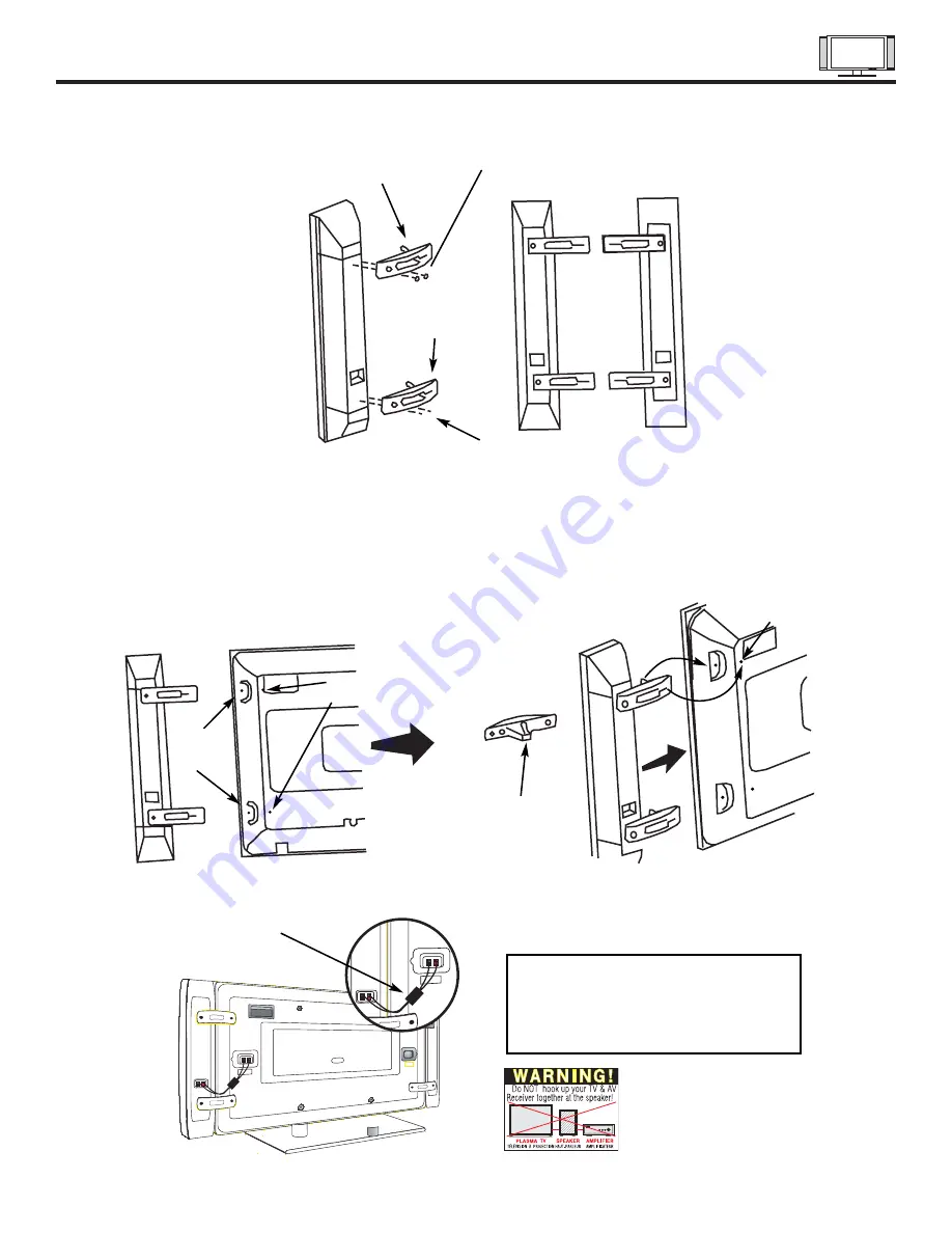
SPEAKER INSTALLATION (MODEL 42HDT20 ONLY)

1.

Screw the speaker holder to the speakers as shown below.

2.

Loosen 4 screws (A) (two on the left and two on the right).

3.

Completely unscrew 4 screws (B) (two on the left and two on the right).

4.

Hook the speaker holders to the loosened screws (A).

5.

Screw the speaker holders to the Display Monitor with screws (B).

6.

Tighten screws (A).

Speaker Holder

Speaker Holder

Screw x2

Screw x2

(R)

(R)                       (L)

(R) Speaker

Loosen
Screw
(A)

Unscrew (B)
Completely

Bottom View
of Speaker
Holder

Hook this
portion to
the loose
screws (A).

Screw in
screws (B)

Insert
horizontally
from the side

7.

Connect the speaker wires as shown below.  (Make sure the core is toward the display monitor side.)

NOTES:

Do not connect speakers

simultaneously to the speaker
terminal of the Plasma TV and
an external amplifier.

Core

Summary of Contents for 32HDT20

Page 1: ...Ch Manager Audio Video Move SEL Sel PO WE R TV VCR CB L DVD 1 2 4 5 6 3 7 8 9 0 INF O SLE EP A V NE T EXIT MEN U CH VO L MUTE PIP PIP CH SW AP FRE EZE PIP MO DE PIP AC CES S VID EO SO UR CE WIZ AR D REC SEL ECT TV RG B ASP ECT STB AN T LAST CH VCR PLUS SVCS GUIDE TV SCHD VID 1 VID 2 VID 3 VID 4 VID 5 TAP E CD AM P MOD E CL U 57 23 TS I 40 63 24 39 Setup Locks Ch Manager Audio Video Move SEL Sel US...

Page 2: ...ns in the literature accompanying the appliance WARNING TO PREVENT FIRE OR SHOCK HAZARD DO NOT EXPOSE THIS PLASMA TELEVISION TO RAIN OR MOISTURE NOTE There are no user serviceable parts inside the AVC center display monitor Model and serial numbers are indicated on back side of the AVC center display monitor POWER SOURCE THIS PLASMA TELEVISION IS DESIGNED TO OPERATE ON 120 VOLTS 60Hz AC CURRENT IN...

Page 3: ...Follow instructions for wall shelf or ceiling mounting as recommended by the manufacturer 17 An outdoor antenna should not be located in the vicinity of overhead power lines or other electrical circuits 18 If an outside antenna is connected to the receiver be sure the antenna system is grounded so as to provide some protection against voltage surges and built up static charges Section 810 of the N...

Page 4: ...the battery compartment 4 Replace the cover BOTTOM VIEW Lift up on tab to remove back cover CAUTION Danger of explosion if battery is incorrectly replaced Replace with the same or equivalent type CAUTION The plasma display wall mount unit WM20 is for use only with Hitachi model 32HDT20 and 42HDT20 REMOTE BATTERIES POWER CORD MONITOR IR MOUSE CONTROL CONNECTION CABLE CABLE 3 4 5 POWER TV VCR CBL DV...

Page 5: ...s A 5 Screw the speaker holders to the Display Monitor with screws B 6 Tighten screws A Speaker Holder Speaker Holder Screw x2 Screw x2 R R L R Speaker Loosen Screw A Unscrew B Completely Bottom View of Speaker Holder Hook this portion to the loose screws A Screw in screws B Insert horizontally from the side 7 Connect the speaker wires as shown below Make sure the core is toward the display monito...

Page 6: ... more NOTES 1 Do not block the ventilation holes of the Plasma Display monitor or the AVC center Blocking the ventillation holes might cuase fire or defect 2 The plasma television has two AC cords one on the AVC center and the other on the Plasma Display monitor In case of an abnormal symptom unplug both AC cords 3 If you purchased the wall mount bracket option please ask for professional installe...

Page 7: ... TV surface temperature is higher than a Cathode ray tube The plasma panel is made from glass Heavy shock on the front panel might damage it When the PDP monitor is transported horizontally the glass panel has the possibility of being broken or increasing the picture defects At the time of transportation horizontal style is prohibited More over please treat the plasma panel with great care because...

Page 8: ...nput connector types required by the various components and the length of each cable 300 Ohm Twin Lead Connector This outdoor antenna cable must be connected to an antenna adapter 300 Ohm to 75 Ohm Phono Connector Used on all standard video and audio cables which connect to inputs and outputs located on the rear jack panel and front control panel F Type 75 Ohm Coaxial Antenna Connector For connect...

Page 9: ... as the cursor down and up buttons when in MENU mode VOLUME level Press these buttons to adjust the sound level The volume level will be displayed on the TV screen These buttons also serve as the cursor left and right buttons when in MENU mode 32HDT20 DISPLAY MONITOR AUDIO VIDEO CONTROL CENTER TruBass AUDIO VIDEO CONTROL CENTER PULL POWER STANDBY RED ON GREEN POWER STANDBY RED ON GREEN INPUT EXIT ...

Page 10: ... the VID5 button on the remote control button and VIDEO 5 appears in the top right corner of the TV screen If you have mono sound insert the audio cable into the left audio jack PHONES JACK Use this jack for your head phones The TV s internal speakers can also be heard Turn off the internal speakers see page 47 if you wish to listen to the head phones only NOTES 1 Your HITACHI Plasma TV will appea...

Page 11: ...ONVERTER allows the ANT A connection to pass directly to a different source such as a cable box only when ANT B is displayed as a main picture Audio Video Inputs 1 2 3 and 4 The VID1 VID4 buttons will select each video source each time they are pressed Use the audio and video inputs to connect external devices such as VCRs camcorders laserdisc players DVD players etc If you have mono sound insert ...

Page 12: ...r and to the display monitors FROM AVC connector IR Blaster This jack provides IR output to your external components VCR Cable box DVD player etc With this connection your external components can automatically be controlled by the A V network feature This connection will allow you to control the external components with your Plasma Television s remote control in TV mode Subwoofer Out Connect the e...

Page 13: ...anel of the AVC box TO MONITOR connectors 3 Insert the other ends of the Monitor Connection Cable to the display monitor rear panel FROM AVC connectors AUDIO MONO L R S VIDEO VIDEO AUDIO MONO L R S VIDEO VIDEO PB PR PB PR R L R L R L ANALOG INPUT RGB 1 DIGITAL INPUT ANT A TO CONVERTER ANT B AUDIO MONO L R S VIDEO VIDEO MONITOR OUT INPUT 4 INPUT 3 Y VIDEO AUDIO L R MONO INPUT 2 AUDIO L R MONO INPUT...

Page 14: ...the input source See page 30 INPUT MODE SELECTION ORDER ANTENNA INPUT VID1 ANT Ant A YPBPR 1 VID1 CONNECTING A MONAURAL AUDIO SOURCE TO INPUT2 INPUT5 1 Connect the cable from the VIDEO OUT of the VCR or the laserdisc player to the INPUT VIDEO jack as shown on the AVC Center below 2 Connect the cable from the AUDIO OUT of the VCR or the laserdisc player to the INPUT MONO L AUDIO jack 3 Press the VI...

Page 15: ...the previous channel AUDIO MONO L R S VIDEO VIDEO AUDIO MONO L R S VIDEO VIDEO PB PR PB PR R L R L R L ANALOG INPUT RGB 1 DIGITAL INPUT ANT A TO CONVERTER ANT B AUDIO MONO L R S VIDEO VIDEO MONITOR OUT INPUT 4 INPUT 3 Y VIDEO AUDIO L R MONO INPUT 2 AUDIO L R MONO INPUT 1 AUDIO AUDIO AUDIO AUDIO OUT Y IR BLASTER RGB 2 TO MONITOR Rear Panel of AVC Center Hitachi Model or Similar Model Back of VCR R ...

Page 16: ...TES 1 Completely insert the connection cord plugs when connecting to rear panel jacks The picture and sound that is played back will be abnormal if the connection is loose 2 A single VCR can be used for VCR 1 and VCR 2 but note that a VCR cannot record its own video or line output INPUT 4 in example on page 22 Refer to your VCR operating guide for more information on line input output connections ...

Page 17: ...jack 6 Press the VID1 VID2 button to view the program from the Laserdisc DVD player or HDTV set top box The VIDEO label disappears automatically after approximately four seconds 7 Press the ANT button to return to the previous channel AUDIO MONO L R S VIDEO VIDEO AUDIO MONO L R S VIDEO VIDEO PB PR PB PR R L R L R L ANALOG INPUT RGB 1 DIGITAL INPUT ANT A TO CONVERTER ANT B AUDIO MONO L R S VIDEO VI...

Page 18: ... ANT B AUDIO MONO L R S VIDEO VIDEO MONITOR OUT INPUT 4 INPUT 3 Y VIDEO AUDIO L R MONO INPUT 2 AUDIO L R MONO INPUT 1 AUDIO AUDIO AUDIO AUDIO OUT Y IR BLASTER RGB 2 TO MONITOR Rear Panel of the AVC Center S VIDEO R L V AUDIO MONO L R S VIDEO VIDEO AUDIO MONO L R S VIDEO VIDEO PB PR PB PR R L R L R L ANALOG INPUT RGB 1 DIGITAL INPUT ANT A TO CONVERTER ANT B AUDIO MONO L R S VIDEO VIDEO MONITOR OUT ...

Page 19: ...onents you wish to control 4 Press the A V NET button on the remote control Use THUMB STICK or to highlight the component you wish to set up Use THUMB STICK to enter component s SOFT KEY control button The A V Network Setup Wizard will automatically start upon the very first use You can access the Setup Menu Wizard again in the future by pressing the A V net button and selecting SETUP NOTES 1 The ...

Page 20: ... TV Channel 03 Channel 04 BACK NEXT HITACHI AV NET Wizard step 5 of 6 Turn ON your VCR then press each of the 3 function keys below Your VCR should respond to one of these keys Now press NEXT to continue BACK NEXT POWER PLAY CH UP HITACHI AV NET Wizard step 6 of 6 Did your VCR respond to POWER PLAY or CH UP Press DONE to finish this wizard or HELP to trouble shoot settings HELP DONE HITACHI AV NET...

Page 21: ...Fisher 0670 GE 0522 0717 GPX 0769 Go Video 0715 Gradiente 0651 Harman Kardon 0582 Hitachi 0573 0664 Hiteker 0672 JVC 0623 0558 Kenwood 0737 0682 0534 Konka 0719 0711 0720 0721 Magnavox 0503 0675 Marantz 0539 Mitsubishi 0521 Onkyo 0627 0503 Optimus 0571 Oritron 0651 Panasonic 0490 0677 0678 0632 Philips 0539 0503 Pioneer 0571 0525 0632 Princeton 0674 Proscan 0522 RCA 0522 0571 0704 0717 Samsung 057...

Page 22: ...VIDEO MONITOR OUT INPUT 4 INPUT 3 Y VIDEO AUDIO L R MONO INPUT 2 AUDIO L R MONO INPUT 1 AUDIO AUDIO AUDIO AUDIO OUT Y IR BLASTER RGB 2 TO MONITOR PROVIDED DIGITAL OUTPUT CAPABILITY PROVIDED PROVIDED DIGITAL OUTPUT AUDIO MONO L R S VIDEO VIDEO AUDIO MONO L R S VIDEO VIDEO PB PR PB PR R L R L R L ANALOG INPUT RGB 1 DIGITAL INPUT OUTPUT Y PB CB PR CR L R VCR 2 V L R OUTPUT S VIDEO V L R INPUT S VIDEO...

Page 23: ... such as DVD players and set top boxes Use these connections in place of the standard video connection if your device has this feature Your component outputs may be labeled Y B Y and R Y In this case connect the components B Y output to the TV s PB input and the components R Y output to the TV s PR input Your component outputs may be labeled Y CBCR In this case connect the components CB output to ...

Page 24: ...ox and press the SET TOP BOX STB button The STB button will blink indicating that the remote will now control your set top box If you have a satellite receiver use this button to program your satellite receiver See page 36 for instructions on how to program the remote to con trol your set top box To operate your DVD player point the remote at the remote sensor of the DVD player and press the DVD b...

Page 25: ...on When the VCR button is pressed it will blink to indicate the remote is in VCR mode see page 34 CABLE CBL When the CABLE button is pressed it will blink to indicate the remote is in CABLE mode see page 35 SET TOP BOX STB When the STB button is pressed it will blink to indicate the remote is in STB mode see page 36 If you have a Satellite receiver use this button to program your Satellite receive...

Page 26: ...Every subsequent press of this button will add 15 minutes to this timer up to a maximum of three hours Once set use INFO when you want to view time remaining If the SLEEP button is pressed while the timer is set it will reset to the original condition INFO button Press this button when you want to check the channel being received the picture source if the channel has stereo ST or second audio prog...

Page 27: ... VIDEO equipment These on screen buttons are called Soft Keys This window shows the available Audio Video equipment soft keys The equipment list will scroll up or down but the selected equipment will always stay on top VCR Move POWER 1 RETURN CH CH SETUP DVD Amplifier Cable Box Set Top Box INFO 2 3 4 5 6 7 8 9 0 VCR Move POWER 1 RETURN CH CH SETUP DVD Amplifier Cable Box Set Top Box INFO 2 3 4 5 6...

Page 28: ... than the black areas 4 3 EXPANDED use this aspect mode to display conventional 4 3 sources by expanding the outer edges of the image to fill the 16 9 screen The center of the image remains unaltered 4 3 Zoom1 Zoom2 Use these aspect modes to zoom in on conventional 4 3 sources 16 9 STANDARD Use this aspect mode to display 16 9 sources like HDTV and DVD s preserving the original 16 9 aspect ratio 1...

Page 29: ...se THUMB STICK to highlight the channel then THUMB STICK to highlight Delete Del and press SELECT to delete To view a Favorite Channel use THUMB STICK to highlight the channel and press SELECT to view 4 RGB1 RGB2 ASPECT DISPLAY MODE PC VGA 480p 720p 1080i PC VGA 480p 720p 1080i PC VGA 480p 720p 1080i REAL REAL REAL 1 X X REAL REAL REAL X X REAL X X X X NORMAL NORMAL NORMAL 1 X X NORMAL NORMAL NORM...

Page 30: ... AUTO See page 63 LAST CHANNEL LAST CH button Use this button to select between the last two channels viewed Good for watching two sporting events etc PICTURE IN PICTURE buttons See separate section on pages 31 33 for a description PIP CH button Use the PIP CH button to select between main picture and sub picture tuning The channel number which is highlighted indicates what channel is being contro...

Page 31: ...of the PIP CH button When the top channel display is highlighted channel tuning is for the main picture When the lower channel display is highlighted channel tuning is for the PIP sub picture The Picture in Picture feature is convenient when you want to watch more than one program at the same time You can watch a TV program while viewing other programs from the ANT A source or any of the video inp...

Page 32: ...ll continuously scan channels in memory see page 59 2 If a channel is changed during this SURF scanning sub pictures will be removed from the screen 3 SURF MODE PIP is allowed only when ANT A is selected as the main channel 4 If MOVIE TV RATINGS LOCK setting is ON PIP SURF mode will be deactivated 5 CLOSED CAPTION will not appear when PIP SURF mode is on NOTES 1 The SWAP button will only operate i...

Page 33: ...ZE button again To change FREEZE modes use the PIP MODE button to cycle through the two modes NOTES 1 Each freeze frame is delayed about 0 1 1 10 second 2 Freeze will only work when PIP is off STROBE FREEZE with PIP OFF PIP should be in SURF mode Press the FREEZE button to freeze three frames of the picture you are currently viewing Press this button again or PIP to return to normal viewing This f...

Page 34: ... your VCR NOTES 1 If your VCR cannot be operated after performing the above procedures your VCR s code has not been precoded into the remote 2 In the unlikely event that your VCR cannot be operated after performing the above procedures please consult your VCR operating guide 3 The remote control will remember the codes you have programmed until the batteries are removed from the remote control Aft...

Page 35: ...6 The remote will now control your Cable box NOTES 1 If your cable box cannot be operated after performing the above procedures your cable box code has not been precoded into the remote 2 In the unlikely event that your cable box cannot be operated after performing the above procedures please consult your cable box operating guide 3 The remote control will remember the codes you have programmed un...

Page 36: ... box satellite receiver does not turn off try a different two digit preset code 6 The remote will now control your set top box satellite receiver NOTES 1 If your set top box satellite receiver cannot be operated after performing the above procedures your set top box satellite receiver code has not been precoded into the remote 2 In the unlikely event that your set top box satellite receiver cannot...

Page 37: ...he DVD player does not turn off try a different two digit preset code 6 The remote will now control your DVD player 7 You will need to set the Display Type of your DVD player to 16 9 Widescreen NOTES 1 If your DVD player cannot be operated after performing the above procedures your DVD player s code has not been precoded into the remote 2 In the unlikely event that your DVD player cannot be operat...

Page 38: ...ry a different two digit preset code 6 The remote will now control your Audio component 7 Repeat steps 1 6 if you wish to program the remote to control another Audio component Be sure to use a different Audio button on the remote since only one component can be programmed per button NOTES 1 If your Audio component cannot be operated after performing the above procedures your Audio component s code...

Page 39: ...12 13 JVC 01 Kenwood 04 Magnavox 05 Mitsubishi 10 Panasonic 04 Phillips 06 Pioneer 03 RCA Proscan 09 Samsung 12 Sanyo 13 Sony 02 Toshiba 05 Yamaha 08 Zenith 05 11 CABLE BRAND CODE ABC 01 07 08 17 18 20 36 37 49 Antronix 39 Archer 11 24 39 Belcor 32 Cable Star 32 Century 11 Citizen 11 Colour Voice 30 42 Comtronics 25 28 Contec 21 Dae Ryung 20 Eastern 14 Electricord 31 Everquest 51 Focus 52 Garrard ...

Page 40: ...3 Press EXIT on the remote control to quickly exit from a menu 4 Press A V NET on the remote control to access the A V Network menu to control external components A V Net EXIT MENU SELECT Setup Locks Ch Manager Audio Video Move SEL Sel This part of the screen shows which selections are available This part of the screen shows which Remote Control buttons to use ...

Page 41: ...ock Choose to lock channel video input and front panel TV Time Lock Set specific time to Lock TV Movie Ratings Block various types of movies and video types based on motion picture ratings TV Ratings Block various types of movies and television programming based on a parental guide ratings Canadian Ratings ENG Block various types of movies and television programming based on the Canadian ratings s...

Page 42: ...y the selected mode will reset to the initial conditions as explained above If RESET is selected in SPORTS mode only SPORTS MODE will return to factory conditions Press EXIT to quit menu or select PICTURE MODE to return to previous menu Use this function to choose from automatic picture settings to optimize your TV s performance Picture Mode MENU THUMB STICK THUMB STICK SELECT THUMB STICK SELECT C...

Page 43: ...ity when using the COMPONENT VIDEO Y PbPr input jacks 3 If you are using the COMPONENT VIDEO input jacks Y PbPr and notice that the TINT and COLOR are abnormal check to make sure that VIDEO Color System is set properly Use this function to adjust flesh tones so they appear natural Tint Use this function to adjust the amount of fine detail in the picture Sharpness This function allows you to automa...

Page 44: ...ARPNESS feature is disabled Black Level Expansion The BLACK LEVEL EXPANSION function automatically enhances shadow detail in dark scenes Black Side Panel The BLACK SIDE PANEL function turns the gray side bars on off when watching 4 3 signals in Standard mode When the Plasma Television is powered OFF BLACK SIDE PANEL feature will be set to OFF automatically when the TV is powered ON BLACK SIDE PANE...

Page 45: ...K Advanced Settings Advanced Settings L R 50 50 L R This function controls the low frequency audio to all speakers Press THUMB STICK to select menu item Press THUMB STICK or to adjust the function Press EXIT to quit the MENU or select Audio to return to the main menu NOTE If TREBLE is selected you are adjusting treble The additional menu items Bass and Balance can be selected and adjusted in the s...

Page 46: ...s technology is incorporated under license from SRS Labs Inc To enter SOUND ENHANCEMENT use THUMB STICK or to highlight then press down on THUMB STICK to select SOUND ENHANCEMENT of your choice Use the THUMB STICK to highlight your sound enhancement choice and press SELECT to select your choice TruBass is an audio enhancement technology from SRS Labs that provides deep rich bass on any speaker sys...

Page 47: ... box it is ON Advanced Settings THUMB STICK SELECT Audio Move SEL Return Advanced Settings Sound Enhancement Balance Bass Treble Audio Audio Source Stereo Mono 2nd Audio Prog Internal Speakers ON Off Advanced Settings Move SEL Select Auto Noise Cancel Perfect Volume 50 50 L R Internal Speaker This function is useful when setting up the external speakers If you prefer to use only speakers from a se...

Page 48: ...add Scan On or erase Scan Off additional channels while in Channel Manager THUMB STICK to highlight the channel num ber then THUMB STICK or to highlight other channels Once the desired channel is highlghted THUMB STICK to scan col umn then THUMB STICK or to select ON or OFF THUMB STICK Ch Manager Move SEL Return Ant A Ch Scan Ch ID Lock 2 Off 3 Off 4 Off 5 Off 6 Off 7 Off 8 Off 9 Off Ch Manager Mo...

Page 49: ...CHANNEL ID for both antenna inputs will be the same 2 CHANNEL ID will be displayed only when channel is displayed as main picture Channel ID Channel Manager Move Edit A Z 0 9 _ Ant A Ch Scan Ch ID Lock 2 On 3 On 4 Off 5 Off 6 Off 7 Off 8 Off 9 Off Channel Manager SEL Return Ant A Ch Scan Ch ID Lock 2 On A 3 On 4 Off 5 Off 6 Off 7 Off 8 Off 9 Off Channel Manager Ant A Ch Scan Ch ID Lock 2 On A 3 On...

Page 50: ...NEL LOCK SET INPUT LOCK and SET FRONT PANEL LOCK can be set individually When SET CHANNEL LOCK is turned on the picture and sound for the chosen channel will be blocked out When SET INPUT LOCK is turned on the picture and sound for all video inputs and the picture and sound for channels 3 4 will be blocked out When FRONT PANEL LOCK is turned on all buttons on the Front Panel will be deactivated ex...

Page 51: ... Return Movie Ratings Movie Ratings TV Time Lock Engage Lock Change Access Code Locks Status TV Ratings Move SEL Select Canadian Ratings Eng Canadian Ratings Frn Not Rated G PG PG 13 R NC 17 X MENU THUMB STICK Contains no rating Not Rated NR and Not Applicable NA pro grams Movie has not been rated or ratings do not apply Restricted Under 17 requires accompanying parent or adult guardian Parents st...

Page 52: ...ogram may include mild physi cal or comedic violence or may frighten chil dren under the age of 7 All children The themes and elements in this program are specifically designed for a very young audience including children from ages 2 6 General audience It contains little or no vio lence no strong language and little or no sex ual dialogue or situations TV Y TV Y7 TV G TV PG TV 14 TV MA Parents str...

Page 53: ... depictions of violence will be infrequent discreet of low intensity and will show the consequences of the acts Other Content Guidelines There will be no profanity nudity or sexual content General Audience Violence Guidelines Will contain very little violence either physi cal or verbal or emotional Will be sensitive to themes which could frighten a younger child will not depict realistic scenes of...

Page 54: ...neral Not recommended for young children Programming intended for a broad audience but contains light or occasional violence that could disturb young children Viewing with an adult is therefore recommended for young children under the age of 8 who can not differentiate between real and imaginary portrayals General Programming intended for audiences of all ages Contains no violence or the vio lence...

Page 55: ...ces Set The Language English Français Español Set The Menu Background Shaded Solid Set The Channels Set The Clock Screen Saver Menu Preference Setup Set The Inputs Move SEL Select Set Event Timer Set Closed Captions MENU THUMB STICK Setup Move SEL Select Menu Preferences Set The Language English Français Español Set The Menu Background Shaded Solid THUMB STICK Setup Setup Locks Ch Manager Audio Vi...

Page 56: ...K to highlight Screen Saver s Main Picture Moving options Press down on THUMB STICK to select and EXIT to quit Option 1 The whole picture will shift every 20 minutes by two pixels Option 2 The whole picture will shift every 40 minutes by two pixels Option 3 The whole picture will shift every 60 minutes by two pixels Screen Wipe If pattern mark occurs use Screen Wipe White Field Signal for at least...

Page 57: ...STICK or to change position Press EXIT to quit the menu Set The Clock THUMB STICK SELECT Set The Channels Set The Clock Screen Saver Menu Preference Setup Set The Inputs Move SEL Select Set Event Timer Set Closed Captions Setup Move SEL Return Set The Clock Time Sun AM Setup Move SEL Return Set The Clock Time Sun AM THUMB STICK Set ...

Page 58: ...elect Set Event Timer Set Closed Captions Setup Move SEL Return Set The Channels Ant A Ant B THUMB STICK Setup Move SEL Select Set The Channels Setup Move SEL Return Set The Channels Ant A Source Antenna Cable 1 Cable 2 Auto Channel Scan Start THUMB STICK SELECT THUMB STICK Setup Move SEL Select Set The Channels Ant A Source Antenna Cable 1 Cable 2 Auto Channel Scan Start Ant A Ant B RECEPTION BAN...

Page 59: ...NNEL SCAN for the second antenna input Remember to select the correct ANTENNA CABLE mode before using AUTO CHANNEL SCAN See CHANNEL MANAGER SCAN to add or to erase additional channels Auto Channel Scan THUMB STICK SELECT THUMB STICK Setup Move SEL Cancel Set The Channels Ant A Setup Move SEL Select Set The Channels Ant A Source Antenna Cable 1 Cable 2 Auto Channel Scan Start Setup Move SEL Select ...

Page 60: ...SEL Select Set The Inputs Setup Move SEL Return Set The Inputs List CAM DVD2 VCR CBL LD VCR1 DVD SAT VCR2 DVD1 STB Reset THUMB STICK SELECT Video 1 Rename Video 2 Rename Video 2 Auto Link Video 3 Rename Video 4 Rename Video 5 Rename Video Power Save Video 1 Rename Video 1 Rename Video 2 Rename Video 2 Auto Link Video 3 Rename Video 4 Rename Video 5 Rename Video Power Save Setup Move SEL Select Set...

Page 61: ... TV has been turned on using the AUTO LINK feature it must be reset before AUTO LINK is used again To do this turn your VCR laserdisc or DVD player OFF This feature is now reset and will turn on your TV as described above 2 When using REMOTE CONTROL SENSOR mode any remote control button will substitute for your video input device play button However intended operation is for use with your VCR lase...

Page 62: ...ay or Weekly Sun TV will turn on off at same time every week Press EXIT to quit the menu CAUTION Do not use your TV as a deterrent when away from home by using the On and Off Timers For safety the TV should be turned off when you are away from home Set Event Timer THUMB STICK SELECT Set The Channels Set The Clock Screen Saver Menu Preference Setup Set The Inputs Move SEL Select Set Event Timer Set...

Page 63: ...by region Use THUMB STICK to highlight the function to change then press THUMB STICK to change the function Press EXIT to quit menu or THUMB STICK to return to previous menu Closed Captions are the dialogue narration and or sound effects of a television program or home video which are displayed on the Plasma Television screen Your local TV program guide denotes these programs as or Closed Caption ...

Page 64: ...UT 2 AUDIO L R MONO INPUT 1 AUDIO AUDIO AUDIO AUDIO OUT Y IR BLASTER RGB 2 TO MONITOR RGB ANALOG OUTPUT SET TOP BOX 1 AVC rear panel connection to an exernal component with an analog RGB output DIgital Link Cable Optional AUDIO OUT Audio Cable Optional AUDIO MONO L R S VIDEO VIDEO AUDIO MONO L R S VIDEO VIDEO PB PR PB PR R L R L R L ANALOG INPUT RGB 1 DIGITAL INPUT ANT A TO CONVERTER ANT B AUDIO M...

Page 65: ...nput signal This Plasma Television can accept the following signal formats Recommended Signal List 1 VGA 640 x400 70 10 31 48 2 640 x 480 59 94 31 47 3 640 x 480 72 81 37 86 4 640 x 480 75 00 37 50 5 800 x 600 56 25 35 16 6 800 x 600 60 32 37 88 7 800 x 600 72 19 48 08 8 800 x 600 75 00 46 88 9 VESA 1024 x 768 60 00 48 36 10 1024 x 768 70 07 56 48 11 1024 x 768 75 03 60 02 12 1280 x 1024 60 02 63 ...

Page 66: ...ning indication is shown 9 Monitor Out Both picture and audio are not available 10 Lock Not available 11 Front Panel Lock Available 12 Menu Language Only English is available 13 Auto Link Turn on to TV mode 14 Menu Background Not available 2 The new setting horizontal position vertical position clock and phase of the signal will be stored The monitor can store up to 13 settings in addition to the ...

Page 67: ...t appear at all when receiving a signal which is not supported by this product If the setting is wrong the Display Monitor will display SYNC TTL level H V separate signal RGB INPUT 0 7Vpp NO SYNC SIGNAL INVALID SCAN FREQ Without sync Either horizontal or vertical frequency is inappropriate or out of range NOTE 1 If the Display Monitor cannot display a signal please try AUTO ADJUST to display the s...

Page 68: ...mote control to display the different features in RGB MODE 3 Press the THUMB STICK buttons to highlight a different feature 4 Press EXIT on the remote control to quickly exit from a menu TV RGB EXIT MENU SELECT RGB MODE MENU VIDEO SETUP SEL TO SELECT MOVE EXIT TO QUIT This part of the screen shows which Remote Control buttons to use ...

Page 69: ...lock frequency to reduce the vertical stripe CLOCK PHASE Adjusts the phase to correct blurred or unstable images RESET Recall the factory preset data of the RGB setup settings RGB2 INPUT This item only available with an RGB 2 input INPUT LEVEL Set the preferred input signal level RGB 2 Digital Input Mode Menu AUTO ADJUST Automatically adjust the geometry to fit the screen H POSITION Adjust horizon...

Page 70: ...g contrast COLOR TEMPERATURE BRIGHTNESS CONTRAST VIDEO RGB MODE MENU RESET ENHANCER 50 MEDIUM ON CHANGE VALUE MOVE TO QUIT 50 BLACK SIDE PANEL EXIT COLOR TEMPERATURE BRIGHTNESS CONTRAST VIDEO RESET ENHANCER 50 MEDIUM ON 50 BLACK SIDE PANEL CHANGE VALUE MOVE TO QUIT EXIT RGB MODE MENU Use THUMB STICK or to adjust brightness Press MENU button to return to RGB MODE MENU and EXIT to quit COLOR TEMPERA...

Page 71: ...tings RESET COLOR TEMPERATURE BRIGHTNESS CONTRAST VIDEO RESET ENHANCER 50 MEDIUM ON 50 BLACK SIDE PANEL MOVE TO QUIT EXIT TO RESET SEL RGB MODE MENU The BLACK SIDE PANEL function turns the gray side bars ON OFF when watching 4 3 signals in Standard Mode Press down on THUMB STICK to select BLACK SIDE PANEL ON OFF BLACK SIDE PANEL COLOR TEMPERATURE BRIGHTNESS CONTRAST VIDEO RESET ENHANCER 50 MEDIUM ...

Page 72: ... item Press EXIT to quit V POSITION H POSITION AUTO ADJUST RESET CLOCK PHASE HORIZONTAL CLOCK INPUT LEVEL RGB2 INPUT 0 0 22 0 MODE 1 0 7V CHANGE VALUE MOVE EXIT TO QUIT RGB MODE MENU H POSITION This feature allows you to adjust the horizontal position of the display Use Left Right cursors to adjust the horizontal position Press the MENU button to return to previous menu item Press EXIT to quit V P...

Page 73: ... quit V POSITION H POSITION AUTO ADJUST SET UP RESET CLOCK PHASE HORIZONTAL CLOCK INPUT LEVEL RGB2 INPUT 0 0 22 0 MODE 1 0 7V CHANGE VALUE MOVE EXIT TO QUIT RGB MODE MENU HORIZONTAL CLOCK Adjusts the pixel clock frequency to reduce the vertical stripe V POSITION H POSITION AUTO ADJUST SET UP RESET CLOCK PHASE HORIZONTAL CLOCK INPUT LEVEL RGB2 INPUT 0 0 22 0 MODE 1 0 7V CHANGE VALUE MOVE EXIT TO QU...

Page 74: ...mount of brightness in the picture NOTE This feature is only available in RGB 2 input See page 29 for signal type for Mode 1 and Mode 2 PC VGA 480p 720p 1080i PC VGA 480p 720p 1080i PC VGA 480p 720p 1080i REAL REAL REAL 1 X X REAL REAL REAL X X REAL X X X X NORMAL NORMAL NORMAL 1 X X NORMAL NORMAL NORMAL X X NORMAL X X X X FULL FULL FULL 1 FULL 2 FULL 2 FULL FULL FULL 3 FULL 2 FULL 2 FULL FULL FUL...

Page 75: ...chemically treated cloth Do not place rubber or vinyl products or cellophane tape on your Plasma Television Avoid repeatedly touching the screen Do not subject the remote control to shocks such as dropping it on the floor etc This may cause physical damage to the precision parts Avoid placing the remote control in a high humidity place or getting it wet Do not leave it on or near a heater Excessiv...

Page 76: ...y from Radio Adjust Radio antennas in order for the monitor not to receive interference The antenna cable of Radio should be kept away from the monitor Use a coaxial cable for antenna You can check if this monitor influences Radio receivers by turning off all other equipment other than the monitor If you find a problem receiveing Radio when using the monitor check the instructions mentioned above ...

Page 77: ... u r e p o w e r c o r d i s p l u g g e d i n B e s u r e T V i s s w i t c h e d O N T r y a n o t h e r c h a n n e l s t a t i o n t r o u b l e C h e c k a n t e n n a c o n n e c t i o n s b a c k o f T V C h e c k a n t e n n a f o r b r o k e n l e a d i n w i r e C h e c k f o r l o c a l i n t e r f e r e n c e C h e c k o u t s i d e a n t e n n a A d j u s t C o n t r a s t c o n t r o...

Page 78: ...ssociation IBM PC AT and VGA are registered trademarkds of International Business Machines Corporation of the U S A Apple and Macintosh are registered trademarks of Apple Computer Inc VESA is a trademark of a nonprofit organization Video Electronics Standard Association This Class B digital apparatus meets all requirements of the Canadian Interference Causing Equipment Regulations This Class B dig...

Page 79: ...quipment into an outlet on a circuit different from that to which the receiver is connected Consult the dealer or an experienced radio television technician for help Modifications The FCC requires the user to be notified that any changes or modifications made to this device that are not express ly approved by Hitachi Home Electronics America Inc may void the user s warranty Cables Connections to t...

Page 80: ...vel 470mVrms RGB1 0 7Vp p 75 Ohm RGB2 Mode 1 0 7Vp p 75 Ohm Mode 2 1 0Vp p 75 Ohm Outputs Video 1 0Vp p 75 Ohm Audio 470mVrms 1k Ohm Audio MTS Stereo SAP TruBass and Matrix Surround 10W 10W 42HDT20 7W 7W 32HDT20 Soft Mute 50 and 100 Supplied Accesories Illuminated Preprogrammed Remote Control Batteries 9 Monitor Connection Cable 6 AC Cable 2 Optional Accesories 32 Monitor Connection Cable Wall Mou...

Page 81: ...t assistance Our service hotline operator will direct you to the Hitachi Authorized Service Facility nearest you Just present proof of purchase and or delivery receipts to the Hitachi Authorized Service Facility and serv ice will be rendered in accordance with the terms of the limited warranty as stated on your warranty card or operating guide Should you have any questions regarding warranty servi...

Page 82: ...g call for a copy 1 800 HITACHI 1 800 448 2244 Au Canada 1 800 HITACHI 1 800 448 2244 Lundi Vendredi L EST 9 00am 7 00pm Samedi L EST 9 00am 5 00pm Pour de plus amples renseignements sur le service durant la période couverte par la garantie sur le fonc tionnement ou pour de l assistance technique communiquez avec La version française de votre manual se trouve á l extérieur de la boîte Si le manuel...

Page 83: ...NOTES 83 ...

Page 84: ...QR52141 ...

Reviews: