background image

Important

- 3 -

PROTECTION AND LOCATION OF YOUR TELEVISION SET

PROTECTION AND LOCATION OF YOUR TELEVISION SET

OPERATION OF YOUR TELEVISION SET

IF THE TELEVISION SET DOES NOT OPERATE PROPERLY

FOR SERVICING AND MODIFICATION 

12. Do not use the television set

near water, for example, near a
bathtub, washbowl, kitchen sink,
or laundry tub, in a wet
basement, or near a swimming
pool, etc.

Never expose the set to rain or
water.  If the set has been
exposed to rain or water,
unplug set from wall outlet and
refer to qualified service
personnel.

13. Choose a place where light

(artificial or sunlight) does not
shine directly on the screen.

14. Avoid dusty places, since

accumulated dust inside the
chassis may cause failure of the
set when high humidity persists.

15. The set has slots or openings in

the cabinet for ventilation
purposes which provide reliable
operation of the receiver and
protect the TV from overheating.
These openings must not be
blocked or covered.

Never cover the slots or
openings with cloth or other
material.

Never block the bottom
ventilation slots of the set by
placing it on a bed, sofa, rug,
etc.

Never place the set near or
over a radiator or heat register.

Never place the set in a "built-
in" enclosure, unless proper
ventilation is provided.

NO!

TO

O

HO

T!

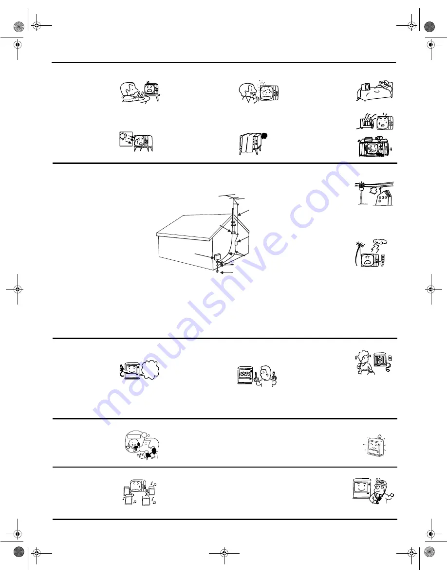
16. If an outside antenna is

connected to the television set,
be sure the antenna system is
grounded so as to provide some
protection against voltage
surges and built- up static
charges. Section 810 of the
National Electrical Code, NFPA
No. 70-1975, provides
information with respect to
proper grounding of the mast
and supporting structure,
grounding of the lead-in wire to
an antenna discharge unit, size
of grounding conductors,
location of antenna discharge
unit connection to grounding
electrode, and requirements for
the grounding electrode.

16-1. Note to CATV system installer: 

(Only for television sets with
CATV reception)  This reminder
is provided to call CATV system
installer’s attention to Article
820-40 of the NEC that provides
guidelines for proper grounding
and, in particular, specifies that
the cable ground shall be
connected to the grounding
system of the building, as close
to the point of cable entry as
practical.

17. An outside antenna system

should not be located in the
vicinity of overhead power lines
or other electrical lights or power
circuits, or where it can fall into
such power lines or circuits.
When installing an outside
antenna system, extreme care
should be taken to keep from
touching such power lines or
circuits as contact with them
might be fatal.

18. For added protection for the

television set during a lightning
storm, or when it is unused for
long periods of time, unplug it
from the wall outlet and
disconnect antenna.  This will
prevent damage due to lightning
and power-line surges. 

No !

ANTENNA

LEAD IN

WIRE

ANTENNA

DISCHARGE UNIT

(NEC SECTION 810-20)

GROUNDING CONDUCTORS

(NEC SECTION 810-21)

GROUNDING CONDUCTORS

POWER SERVICE GROUNDING

ELECTRODE SYSTEM

(NEC ART 250 PART H)

NEC NATIONAL ELECTRICAL CODE

ELECTRIC

SERVICE

EQUIPMENT

GROUND

CLAMP

EXAMPLE OF ANTENNA GROUNDING AS PER NATIONAL ELECTRICAL
CODE INSTRUCTIONS.

19. This television set should be

operated only from the type of
power source indicated on the
marking label. If you are not sure
of the type of power supply at
your home, consult your
television dealer or local power
company.  For television sets
designed to operate from battery
power, refer to the operating
instructions.

20. If the television set does not

operate normally by following the
operating instructions, unplug
the television set from the wall
outlet and refer servicing to
qualified service personnel.
Adjust only those controls that
are covered in the instructions
as improper adjustment of other
controls may result in damage
and will often require extensive
work by a qualified service
technician to restore the
television set to normal
operation.

21. If your television set is to remain

unused for a period of time,
(such as when going on a
holiday), turn the television set
OFF and unplug it from the wall
outlet.

Use

Proper

Voltage

?

22.

If you are unable to restore
normal operation by following
the detailed procedure in your
operating instructions, do not
attempt any further
adjustments.  Unplug the set
and call your dealer or service
technician.

23. Whenever the television set is

damaged or fails, or if there is a
distinct change in performance
that indicates a need for service,
unplug the set and have it
checked by a qualified service
technician.

24. It is normal for some television

sets to make occasional
snapping or popping sounds,
particularly when being turned on
or off.  If the snapping or popping
is continuous or frequent, unplug
the set and consult your dealer or
service technician.

Pop

Snap

Pop

Snap

Service

25. Do not use attachments not

recommended by the television
set manufacturer as they may
cause hazards.

26. When replacement parts are

required, be sure the service
technician has used
replacement parts specified by
the manufacturer that have the
same characteristics as the
original part.  Unauthorized
substitutions may result in fire,
electric shock, or other hazards.

27. Upon completion of any service

or repairs to the television set,
ask the service technician to
perform routine safety checks to
determine that the television is in
safe operating condition.

ASK

ME!

0348E3.fm  Page 3  Tuesday, April 25, 2000  4:15 PM

Summary of Contents for 27UX01

Page 1: ...01B OPERATING GUIDE IMPORTANT SAFEGUARDS 2 3 FIRST TIME USE 4 9 REMOTE CONTROL 10 17 SPECIAL FUNCTIONS 18 29 USEFUL INFORMATION 30 31 Printed in the United States TQB2AA0348 ASK ME 0348E3 fm Page 1 Tuesday April 25 2000 4 15 PM ...

Page 2: ...r to be notified that any changes or modifications made to this device that are not expressly approved by Hitachi Home Electronics America Inc may void the user s authority to operate the equipment 1 This television set is equipped with a polarized alternating current line plug a plug having one blade wider than the other This plug will fit into the power outlet only one way This is a safety featu...

Page 3: ...ion set during a lightning storm or when it is unused for long periods of time unplug it from the wall outlet and disconnect antenna This will prevent damage due to lightning and power line surges No ANTENNA LEAD IN WIRE ANTENNA DISCHARGE UNIT NEC SECTION 810 20 GROUNDING CONDUCTORS NEC SECTION 810 21 GROUNDING CONDUCTORS POWER SERVICE GROUNDING ELECTRODE SYSTEM NEC ART 250 PART H NEC NATIONAL ELE...

Page 4: ...r petroleum based products Television Location This television is intended to be used with a stand or entertainment center Consult your dealer for available options Locate for comfortable viewing Avoid placing where sunlight or other bright lights including reflections will fall on the screen Use of some types of fluorescent lighting may reduce remote control transmitter range Adequate ventilation...

Page 5: ...ts sporadically or stops operating the television Cable Antenna For proper reception either a cable or antenna connection is required Cable Connection Connect the cable supplied by your local cable company Note A cable converter box may be required for proper reception Check with your local Cable company for compatibility requirements Antenna Connection For proper reception of VHF UHF channels an ...

Page 6: ...INPUT button 3 Operate optional equipment as instructed in equipment manual NOTE The S VIDEO connection is optional and overrides normal VIDEO connection Use INPUT 2 AUDIO R and L with S VIDEO connection TO AUDIO AMP VIDEO S VIDEO R AUDIO L COMPONENT VIDEO INPUT PR Y VIDEO PB R L INPUT 1 R AUDIO L INPUT 2 L R AUDIO OUT VIDEO OUT VCR ANT INPUT CABLES NOT SUPPLIED OUTPUT TERMINALS ON BACK OF TV S VI...

Page 7: ...ernal amplifier Digital TV Set Top Box DTV STB Connection Use this diagram to connect a DVD player or a DTV STB Digital TV Set Top Box to the back of your TV Note There are three video inputs Y PB and PR Separate component color inputs provide luminance and color separation Use the L left and R right audio inputs TO AUDIO AMP VIDEO S VIDEO R AUDIO L COMPONENT VIDEO INPUT PR Y VIDEO PB R L INPUT 1 ...

Page 8: ...ntrol to display the PIP frame To view scrambled channels through your cable box in the PIP frame Press the INPUT button on the remote control to select the video input to which your VCR is connected Verify the CABLE BOX and VCR are ON and the VCR tuned to channel 3 or 4 Choose channels for the PIP frame by pressing the CABLE button on the remote control and using the numeric keypad or CH buttons ...

Page 9: ...source in the PIP frame Press the INPUT button on the remote control to select the video input to which your VCR is connected Verify the VCR is on View the external video source in the PIP frame Choose channels for the Main Picture by pressing the TV button on the remote control and using the numeric keypad or CH pq button SWAP and RECALL Buttons The SWAP button switches the PIP and the main pictu...

Page 10: ...ing the TV or VCR this switches TV VCR When controlling cable this switches between A and B Channel Button Press to select channels Cursor Button Press to adjust audio menus video menus and select operating features PIP CH Buttons Press to select PIP channels Lst Ch Last Channel Button Press to switch to the previous channel Recall Button Press to display Time status of Sleep Timer Channel Video M...

Page 11: ...ction for remote control DVD VCR DVD VCR DVD VCR mode selection for remote control PIP TV Displays the PIP frame press button once more and PIP frame becomes smaller SWAP TV Switches PIP and Main picture source MOVE TV Moves the PIP frame to one of four corners of Main picture FREEZE TV Freezes the PIP picture PIP CH pq TV Selects channels for the PIP frame TV VCR TV VCR Selects TV or VCR mode Sel...

Page 12: ...s channel Selects channel Selects chapters TV Selects input mode TV Selects SLEEP timer menu STOP DVD VCR Stop DVD VCR Search Rewind Rewind DVD VCR Play DVD VCR Search Fast forward Fast Forward REC VCR Record DVD VCR Pause C S VCR Commercial skip RECALL TV Displays channel time channel I D and audio mode Key Operates Function Continued VOL VOL 1 2 3 4 5 6 7 8 9 0 INPUT SLEEP 0348E3 fm Page 12 Tues...

Page 13: ...h the CHANNEL p q buttons pressing the LAST CH button will switch between the last two channels scanned Swap Button Press the SWAP button when the PIP frame is displayed to interchange what is being viewed on the main picture with that of the PIP frame Note The audio is from the Main Picture only VIDEO 1 29 1 00 KXYZ CH 3 1 2 3 4 5 STEREO SAP MONO CHANNEL TUNED IMMEDIATELY BEFORE Press Button Pres...

Page 14: ...and PIP video source will display on screen momentarily Audio will be that of main picture Note When the Main Picture is in Video mode with no signal the PIP will not operate properly 2 Press the PIP button again to size PIP frame or twice to cancel PICTURE IN PICTURE feature PIP CH Buttons Press the PIP CHANNEL p q button while the PIP frame is displayed to sequentially scan through channels PIP ...

Page 15: ...displayed will freeze action from the PIP frame Press the FREEZE button again to continue action Press the PIP button as needed to delete PIP frame Move Button The PIP frame may be located at any corner of the Main Picture by pressing the MOVE button when the PIP frame is displayed Note As MOVE button is pressed when the PIP frame is displayed the PIP frame will move counterclockwise as illustrate...

Page 16: ...tton if required Cable Satellite Box Functions This remote is designed to operate different brands of cable boxes and Satellite boxes You must first program the remote to match the remote system in your cable satellite box Procedure 1 Turn ON your cable satellite box 2 Aim the remote control at the front of your cable satellite box 3 While holding down the CABLE button on the remote enter the 2 di...

Page 17: ...on 20 21 22 23 24 Fisher 34 37 38 39 GE 33 GO VIDEO A 43 GO VIDEO 8 44 Goldstar 8 36 Hitachi 00 01 02 03 04 05 06 JVC 18 49 50 51 Magnavox 12 13 Mitsubishi 27 28 29 30 NEC 40 41 Panasonic 10 11 Philips 14 Pioneer 13 14 Samsung 17 25 26 Scott 16 Sharp 31 32 Shintom 19 Sony 07 08 09 Symphonic Teknika 42 Teknica 46 Toshiba 15 Zenith 35 Brand Code General Instrument 30 Hitachi 29 Hughes 36 Panasonic 3...

Page 18: ...level CH Channel Press to select programmed channels Menu Button Press to display main menu and access onscreen features or Adjustment menus Input Button Press to select TV or video input Front Control Panel POWER VOL VOL CH CH MENU INPUT 1 2 3 4 5 HITACHI 1 2 3 4 5 0348E3 fm Page 18 Tuesday April 25 2000 4 15 PM ...

Page 19: ... the main menu and submenus Press the EXIT button on the remote control to exit menus Cursor Buttons Press the cursor buttons to select an icon to highlight the desired features or to select and adjust features Cursor Buttons MENU 0348E3 fm Page 19 Tuesday April 25 2000 4 15 PM ...

Page 20: ...or decrease the treble response Balance Emphasize the left right speaker volume Mode Select the audio mode STEREO Two channel audio reception SAP Second Audio Program Tune to the alternate audio channel if available in your area bilingual or descriptive audio MONO One channel audio Use when stereo signal is weak Perfect Vol Automatically adjust volume to maintain a comfortable listening level Surr...

Page 21: ...Adjust dark areas for crisp detail Contrast Adjust white areas of picture Sharpness Adjust for best clarity of outline detail CHANNEL ID Channel I D Provide labels for up to 30 stations using up to four characters for each station LOCK Quick Lock Program to prevent video games cable box and VCRs from being viewed MENU DESCRIPTION 0348E3 fm Page 21 Tuesday April 25 2000 4 15 PM ...

Page 22: ...e SET UP icon 3 Press to display the SET UP menu 4 Press cursor q highlight PROG CHAN 5 Press cursor t or u to select ANTENNA TV or CATV 6 Press to exit menu Auto Channel Set This feature places all channels with a video signal into channel scan memory Note This feature is disabled when Lock Set is activated 1 Press 2 Press cursor p or q and t or u to highlight the SET UP icon 3 Press to display t...

Page 23: ...ight the SET UP icon 3 Press to display the SET UP menu 4 Press cursor q to highlight CC CLOSED CAPTION 5 Press cursor t or u to select NO C1 or C2 6 Press to exit menu Closed Caption This receiver has a built in decoder that provides a visual depiction of the audio portion of a television program It allows the viewer to read the dialogue of a television program or other information 1 Press 2 Pres...

Page 24: ...ining Video Adjustments 8 Press to exit menu Reset Use to reset Color Tint Brightness Contrast and Sharpness adjustments back to a factory preset level 1 Press 2 Press cursor porqand toru to highlight VIDEO icon 3 Press to display the VIDEO menu 4 Press cursor u to highlight COLOR 5 Press cursor q to highlight RESET 6 Press cursor t or u to select RESET to normalize color tint brightness contrast ...

Page 25: ...o a factory preset level Note Bass and Treble is automatically set when PERFECT VOL VOLUME is ON 1 Press 2 Press cursor porq and tor u to highlight AUDIO icon 3 Press to display the AUDIO menu 4 Press cursor p or q to highlight RESET 5 Press cursor u to select SET to normalize Bass Treble and Balance 6 Press to exit menu Perfect Vol Volume This feature automatically adjusts the volume to maintain ...

Page 26: ...the TV remote to control the volume muting bass treble and balance of the External Amplifier System é OFF FAO Fixed Audio Output TV SPEAKERS off sound output is not adjustable The audio is controlled by the External Amplifier System volume control 7 Press to exit menu TIMER Clock Set Clock when set will display onscreen at initial Turn On after a channel change and when pressing the RECALL button ...

Page 27: ...ight ENTER CHANNEL 12 Press cursor t or u or use the remote control keypad to enter the desired channel number 13 Press cursor q to highlight SET 14 Press cursor u to select YES or NO 15 Press to exit menu Note To deactivate program timer select no in step 13 CUSTOM Custom Favorites In CHANNELS menu under FAVORITES select CHANNEL SCAN FAV to enter up to 16 favorite channels CHANNEL SCAN ALL to sca...

Page 28: ...cter then repeat until all characters are entered 11 Press p or q highlight ENTER CHANNEL 12 Repeat steps 7 11 to continue adding Station Identifiers 13 Press to exit menu Note To delete a Manual Caption Channel I D station Identifier from memory all four characters positions in the ENTER CAPTION area must display a dash mark Input Label 1 Press 2 Press cursor p or q and t or u to highlight CUSTOM...

Page 29: ...ess then press cursor q to highlight HOW LONG 9 Press cursor u to select the desired amount of time 12 24 48 hours or ALWAYS for Lock Set to be activated 10 Press to exit menus To unlock Lock Set follow steps 1 through 6 and on step 6 select OFF Note If Lock Set is selected and if a blocked channel or video input is selected the message Locked displays on the TV screen For more information about M...

Page 30: ...G MUTE CONTROL IF APPLICABLE TRY ANOTHER CHANNEL TV SPEAKERS OFF NO VIDEO NOISY SOUND TV OR CABLE TUNING MODE SET TO PROPER SETTING ANTENNA INPUT CORRECT IF APPLICABLE NO PICTURE NO SOUND CHECK THAT AC POWER CORD IS PLUGGED INTO AC OUTLET BRIGHTNESS AND AUDIO CONTROLS SET PROPERLY TRY ANOTHER CHANNEL NO COLOR NORMAL SOUND COLOR CONTROL SETTINGS TRY ANOTHER CHANNEL BLACK PICTURE NO SOUND RECEIVER I...

Page 31: ...Our service hotline operator will direct you to the Hitachi Authorized Service Facility nearest you Just present proof of purchase and or delivery receipts to the Hitachi Authorized Service Facility and service will be rendered in accordance with the terms of the limited warranty as stated on your warranty card or operating guide Should you have any questions regarding warranty service operation o...

Page 32: ... 0348E3 fm Page 32 Tuesday April 25 2000 4 15 PM ...

Reviews: