1
»
ELECTRICAL SPECIFICATIONS ......................................................................................................... 1
»
IMPORTANT SERVICE SAFETY PRECAUTION ................................................................................. 2
»
LOCATION OF USER'S CONTROL ..................................................................................................... 6
»
INSTALLATION AND SERVICE INSTRUCTIONS ................................................................................ 7
»
CHASSIS LAYOUT ............................................................................................................................. 13
»
BLOCK DIAGRAM .............................................................................................................................. 14
»
SCHEMATIC DIAGRAMS ................................................................................................................... 15
»
PRINTED WIRING BOARD ASSEMBLIES ........................................................................................ 22
»
REPLACEMENT PARTS LIST ............................................................................................................ 25
»
PACKING OF THE SET ...................................................................................................................... 33
Page
POWER INPUT .................................................... 120 V AC 60 Hz
POWER RATING .................................................................. 110 W
PICTURE SIZE ........................................... 2,187cm
2
(339sq inch)
CONVERGENCE ............................................................. Magnetic
SWEEP DEFLECTION .................................................... Magnetic
FOCUS ............................................... Hi-Bi-Potential Electrostatic
INTERMEDIATE FREQUENCIES
Picture IF Carrier Frequency ..................................... 45.75 MHz
Sound IF Carrier Frequency ...................................... 41.25 MHz
Color Sub-Carrier Frequency .................................... 42.17 MHz
(Nominal)
AUDIO POWER
OUTPUT RATING .............. 1.3W + 1.3W (at 10% distortion and
Dual CH Operate)
CONTENTS
ELECTRICAL SPECIFICATIONS
SPEAKER
SIZE ...................................................................... 8 cm (Round)
VOICE COIL IMPEDANCE ............................ 32 ohm at 400 Hz
ANTENNA INPUT IMPEDANCE
VHF/UHF ..................................................... 75 ohm Unbalanced
TUNING RANGES
VHF-Channels ............................................................... 2 thru 13
UHF-Channels ............................................................ 14 thru 69
CATV Channels ........................................................... 1 thru 125
(EIA, Channel Plan U.S.A.)
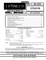
PA
No. 0137
27CX01B
R/C: CLU-341U
SERVICE MANUAL
CAUTION:
Before servicing this chassis, it is important that the service technician read the "Safety Precaution" and "Product
Safety Notices" in this service manual.
In the interests of user-safety (Required by safety regulations in some countries) the set should be restored to its
original condition and only parts identical to those specified should be used.
SAFETY NOTICE
USE ISOLATION TRANSFORMER WHEN SERVICING
Components having special safety characteristics are identified by a
å
on the schematics and on the parts list in this Service Data
and its supplements and bulletins. Before servicing the chassis, it is important that the service technician read and follow the "Safety
Precautions" and "Product Safety Notices" in this Service Manual.
*For continued x-radiation protection, replace picture tube with original type of Hitachi approved equivalent type.
SPECIFICATIONS AND PARTS ARE SUBJECT TO CHANGE FOR IMPROVEMEN
SOLID STATE COLOR TELEVISION
MAY 2000 HHEA-MANUFACTURING DIVISION
TENTATIVE
Summary of Contents for 27CX01B
Page 14: ...14 8 7 10 9 6 5 4 3 2 1 A B C D E F G H BLOCK DIAGRAM 6 5 4 3 2 1 A B C D E F G H ...
Page 16: ...17 16 12 11 10 9 8 7 6 5 4 3 2 1 A B C D E F G H SCHEMATIC DIAGRAM MAIN 1 Unit ...
Page 17: ...19 18 12 11 10 9 8 7 6 5 4 3 2 1 A B C D E F G H SCHEMATIC DIAGRAM MAIN 2 Unit ...
Page 19: ...21 6 5 4 3 2 1 A B C D E F G H SCHEMATIC DIAGRAM S VIDEO Unit ...
Page 20: ...22 6 5 4 3 2 1 A B C D E F G H PWB A MAIN Unit Wiring Side PRINTED WIRING BOARD ASSEMBLIES ...
Page 21: ...23 6 5 4 3 2 1 A B C D E F G H PWB A MAIN Unit Chip Parts Side ...
Page 32: ...Ref No Part No Description Ref No Part No Description 34 ...


