background image

6

After stapling:
(1) disconnect air hose from the stapler;
(2) remove all staples from the stapler;
(3) supply 5 – 10 drops of Hitachi pneumatic tool

lubricant into the air plug on the stapler; and

(4) open the petcock on the air compressor tank to

drain any moisture.

Under low temperature conditions, the machine
sometimes does not operate correctly. Always operate
the machine at the appropriate ambient temperature.

2. How to adjust the stapling depth

To assure that each staple penetrates to the same
depth, be sure that:
(1) the air pressure to the stapler remains constant

(regulator is installed and working properly), and

(2) the stapler is always held firmly against the

workpiece.

If staples are driven too deep or shallow into the

workpiece, adjust the stapling in the following order.

CAUTIONS:

Before adjustment, always disconnect the hose
and release compressed air in the power tool.

During adjustment always keep your finger off the
trigger.

During adjustment make sure that no part of the
body, hands, or legs is ever in front of the staple
outlet.

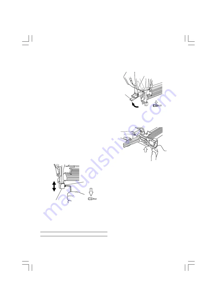
Please carry out adjustments in the following order.

(See 

Fig. 7

)

To adjust the driven-in depth of a staple, loosen the

screw that secures a push lever piece.

If the staple is driven in deeply, adjust the push lever

piece to ”down”, and if it’s driven in shallowly, adjust
the push lever piece to “up”.

Tighten the screw to fasten the push lever piece.

Fig. 7

NOTE:

Please use the minimum air pressure that is sufficient
to drive the staples to a suitable depth. If an overly
high pressure is used, the life of the piston damper
etc. will be shortened.

INSPECTION AND MAINTENANCE

CAUTION:

Be sure to disconnect the hose during cleaning
jams, inspection, maintenance and cleaning.

1. Countermeasure for staple jamming

(1) Remove all staples.
(2) Release the lock lever and open the blade guide. (See

Fig. 8

)

Fig. 8

(3) Remove the jammed staple with a slotted-head

screwdriver. (See 

Fig. 9

)

Fig. 9

(4) Close the blade guide and latch.
(5) In case of frequent jam, contact a Hitachi authorized

service center.

2. Inspection and maintenance

Periodically inspect the device.

(1) Remove the four hexagon socket hd. bolts securing

the exhaust cover and remove the exhaust cover.
Then, cylinder, piston, and other parts can be removed
in respective assembly groups.
Wipe the drive bit, the piston sliding part and the body
interior with a cloth to remove deposited dirt.

(2) Confirm that the piston damper offers normal

operation. A damaged piston damper may cause
damage to other component parts.

(3) Carefully check the O-ring for wear while

disassembling. A worn or  damaged O-ring may
deteriorate overall performance. Replace a worn or
damaged O-ring with new one.

(4) Prior to reassembling the device, apply grease

(Attolub No. 2 Grease) to the O-ring. Also, lubricate
the device with the recommended oil.

3. Check on mounting screws for each part

At regular intervals check every part for loose
mounting screws and whether or not there are any
air leaks. Retighten any loose screws. Operating the
equipment with loose screws untightened will incur
a hazard.

Push Lever Piece

Screw

Disconnect air hose

Blade Guide

Lock Lever

Disconnect air hose

01Eng_N5008AC2_Eng

08/7/31, 22:46

6

Summary of Contents for N 5008AC2

Page 1: ...8AC2 Stapler Read through carefully and understand these instructions before use Keep this Manual available for others before they use the Stapler Handling instructions 001Cover_N5008AC2_Eng 08 7 31 22 45 1 ...

Page 2: ...d only for authorized service center PRECAUTIONS ON USING STAPLER 1 Safe operation through correct usage This tool was designed for driving staples into wood and similar materials Use it for its intended purpose only 2 Make sure air pressure is within the rated range of air pressure Fastener driving tools operated by compressed air shall only be connected to compressed air lines where the maximum ...

Page 3: ...aple currently being driven in comes into contact with a previous staple or a knot in the wood 17 Take care when stapling thin boards or the corners of wood When stapling thin boards the staples may pass right through as may also be the case when stapling the corners of wood due to deviation of the staples In such cases always make sure that there is no one and nobody s hands or feet etc behind th...

Page 4: ...5 mm L 258 mm H 76 mm W 14 3 8 10 5 32 3 Weight 2 0 kg 4 4 lbs Hose inside diam 6 mm 1 4 SPECIFICATIONS Piston Piston O Ring Driver Blade Nose Lock Lever Blade Guide Push Lever Firing Head outlet Push Lever Piece Staple Feeder Magazine Assembly Magazine Cover Air Plug Cap Body Trigger Exhaust Cover Fig 1 NAME OF PARTS 01Eng_N5008AC2_Eng 08 7 31 22 46 3 ...

Page 5: ...ng cycles 2 It is recommended using the recommended oil SHELL TONNA Other applicable oils are listed Never mix two or more types of different oils 3 Load staples CAUTIONS 䡬 When loading staples into stapler 1 do not depress trigger 2 do not depress push lever and 3 keep your face hands feet and other body parts as well as those of other persons away from the nose muzzle to avoid possible injury du...

Page 6: ...t several staples instead of just one in rapid succession when strongly pressed flush against a surface or when using on hard materials In such cases fire the staples by squeezing and quickly releasing the trigger 2 Push lever When depressing the staple outlet be sure to fully lift the push lever See Fig 5 to release the safety lock Thus staples cannot be driven without releasing the safety lock e...

Page 7: ... to a suitable depth If an overly high pressure is used the life of the piston damper etc will be shortened INSPECTION AND MAINTENANCE CAUTION Be sure to disconnect the hose during cleaning jams inspection maintenance and cleaning 1 Countermeasure for staple jamming 1 Remove all staples 2 Release the lock lever and open the blade guide See Fig 8 Fig 8 3 Remove the jammed staple with a slotted head...

Page 8: ...egulations and standards prescribed in each country must be observed MODIFICATIONS Hitachi Power Tools are constantly being improved and modified to incorporate the latest technological advancements Accordingly some parts may be changed without prior notice COMPRESSOR CAUTION When the maximum operating pressure of the air compressor exceeds 8 3 bar 120 psi be sure to provide a reducing valve betwe...

Page 9: ...8 02Back_N5008AC2_Eng 08 7 31 22 46 8 ...

Page 10: ...9 02Back_N5008AC2_Eng 08 7 31 22 46 9 ...

Page 11: ... 1 37 HEX SOCKET HD BOLT M5 16 3 38 AIR PLUG NPT 1 4 1 39 VALVE GUARD 1 40 ROLL PIN D3 45 1 41 HITACHI PLATE 1 42 NYLOCK BOLT W FLANGE M5 8 2 43 GUARD 1 44 HANDLE ARM 1 45 WARNING LABEL 1 46 MAGAZINE COVER 1 47 WASHER 1 48 HEX SOCKET HD BOLT M5 18 1 49 PLUNGER SPRING 1 50 PLUNGER A 1 51 PLUNGER O RING 1 52 O RING S 12 3 53 VALVE BUSHING 1 54 PLUNGER B 1 55 VALVE PACKING 1 56 URETHANE BALL C D7 14 ...

Page 12: ...Hitachi Koki Co Ltd 809 Code No C99173911 Printed in Taiwan 02Back_N5008AC2_Eng 08 7 31 22 46 11 ...

Reviews:

Related manuals for N 5008AC2