


ELECTRICAL COMPONENTS
- 305 -
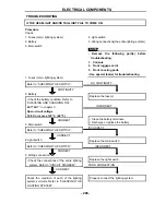
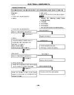
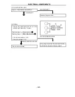
Test steps 1 & 2: Heating phase
Test steps 3 & 4: Cooling phase
WARNING
:
Handle the thermo switch 1 with special
care.
Never subject it to a strong shock or allow
it to be dropped. Should it be dropped, it
must be replaced.
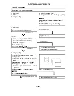
GOOD CONDITION
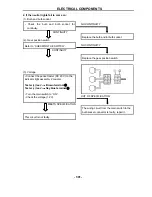
(3). Voltage
• Connect the pocket tester (DC 20 V) to the
indicator light assembly 1 coupler.
Tester (+) lead
Brown terminal
①
Tester (–) lead
White/Blue terminal
②
• Turn the main switch to “ON”.
• Check the voltage (12 V).
BAD CONDITION
Replace the thermo switch 1
OUT OF SPECIFICATION
The wiring circuit from the main switch to the
bulb socket connector is faulty, repair it.
Summary of Contents for HS800UTV 2014
Page 91: ...SPECIFICATIONS 79 HYDROGRAPHIC CHART Hydrographic chart Pressure ...
Page 92: ...SPECIFICATIONS 80 LUBRICATION OIL WAY LUBRICATION OIL WAY Pressure splashing oil ...
Page 289: ...CHASSIS 277 Fuel tank cap Remove the fuel tank cap by turning it counterclockwise ...
Page 353: ......
Page 354: ......
Page 355: ......
Page 356: ......
Page 357: ......
Page 358: ......
Page 359: ......
Page 360: ......
Page 361: ......


