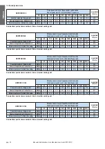
c) Unit Model Code Setting (DSW4)
No setting is required.
Setting the model code of the indoor unit.
d) Refrigerant Cycle No. Setting (RSW2&DSW5)
Setting is required.
Setting positions before shipment, are all OFF.
e) Fuse Recover (DSW7)
*Factory Setting
*In the case of applying high voltage to the terminal
1,2 of TB2, the fuse (0,5A) on the PCB1, is cut.
In such a case, firstly connect the wiring to TB2, and
then turn on No.1 pin.
f) Optional function Setting (DSW8)
No setting is required.
Setting positions before shipment, are all OFF.
NOTE
The “
■
” mark indicates positions of dip switches.
Figures show setting before shipment.
CAUTION
Before setting dip switches, firstly turn OFF power source and
then set the position of the dip switches. If the switches are set
without turning OFF the power source, the switches can not
function.
pag. 38
Installation, Use and Maintenance Manual - HKFD1EC/C Series
English
SECTION 4 - ELECTRICAL CONNECTIONS
• The electrical connections to the control cabinets must be carried out by specialized staff, following the supplied wiring diagrams.
• Make sure that the voltage and the frequency specified on the nameplate correspond to those of the power supply line.
• For the main supply of the regenerator is not allowed to use adapters, multiple sockets and/or cable extensions.
• The installer must foresee the installation of the cut-off switch and of everything that is necessary for the protection of the electri-
cal components, as close as possible to the unit.
• Connect the unit to an effective earth, using the appropriate screw fitted on the unit.
Before beginning whichever operation make sure that the voltage supply is cut off.
Carry out the connection with cables of a section which is adapted to the engaged power and in the respect of the local norms.
Their dimension must however allow to realize a voltage drop of less than 3% during the starting phase.
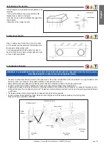
4.1 Setting of Dip Switches on PCB1 in electrical box1
1) Turn OFF all the power supply to the indoor and the outdoor
units before dip switch setting. If not, the setting is invalid.
2) The dip switch positions are as follows:
3)The PCB1 in the unit is equipped with 2 rotary switches and 6
dip switches.
Before testing unit, set these dip switches according to the following
instructions.
Unless these dip switches are set in the field, the unit can not be
operated.
a ) Unit No. Setting (RSW1&DSW6)
Setting is required. Set the unit No. of all indoor units respectively and
serially by following setting position shown in the table below.
b) Capacity Code Setting (DSW3)
No setting is required, due to setting before shipment. This switch is
utilized for setting the capacity code which corresponds to the Horse
Power of the indoor unit.
Before shipment. DSW6 and RSW1 are set to "0".
Max.64 units are available to set when all the equipment
to be connected are corresponding to Hi-NET.
Max.16 units when the units corresponding/
non-corresponding to Hi-NET are combined.
Setting
Position
Set by inserting
slotted screwdriver
into the groove
DSW6 (Tens. Digit)
RSW1 (Units Digit.)
Ex.) Set at No.16 Unit
DSW6
Set No.1 Pin ON
RSW1
Set at "6"
Unit No. Setting
Capacity 09 17 18
Setting
Position
Before shipment. DSW5 and RSW2 are set to "0".
Max.64 cycles are available to set when all the equipment
to be connected are corresponding to Hi-NET.
Max.16 cycles when the units corresponding/
non-corresponding to Hi-NET are combined.
Setting
Position
DSW5 (Tens. Digit)
RSW2 (Units Digit.)
Ex.) Set at No.5 Cycle
Set All Pins OFF
RSW2
Set at "5"
Refrigerant Cycle No. Setting
DSW5
Set by inserting
slotted screwdriver
into the groove


