- 20 -
8
、
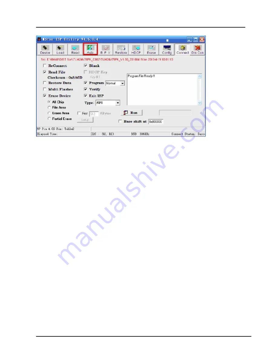
Click the “
Run”
button and wait update end
.
If show any error message
,
then do “
Dis Con
” >> “
Connect
”
and click the “
Run
” button
again
till show the following dialog window
。
Page 1: ...LCDTelevision Service Manual Chassis MSD309PX Ver 1 0 Hisense Electric Co Ltd March 2011...
Page 2: ...Diagram 13 3 Factory Service OSD Menu and Adjustment 15 3 1 To enter the Factory OSD Menu 15 3 2 Factory OSD Menu 15 4 Software Upgrading 17 4 1 Upgrading with the ISP_TOOL 17 4 2 Upgrading with the U...
Page 3: ...signed for the purpose The special tools should be used when and as recommended It is important to note that this manual contains various CAUTIONS and NOTICES which should be carefully read in order t...
Page 4: ...racteristics may create shock fire or other hazards Under no circumstances should the original design be modified or altered without written permission from Hisense Hisense assumes no liability expres...
Page 5: ...blade exposure To prevent electrical shock match wide blade or plug to wide slot fully insert 1 1 4 When replacement parts are required be sure to use replacement parts specified by the manufacturer...
Page 6: ...wer Continuing to use the product may cause fire or electric shock 5 If the product emits smoke and abnormal smell or makes an abnormal sound immediately turn off the power Continuing to use the produ...
Page 7: ...e safety of the product and the servicing work Be sure to follow these instructions Before starting the work secure a sufficient working space At all times other than when adjusting and checking the p...
Page 8: ...cuit board be sure to remove static electricity from your body before handling the circuit board Be sure to handle the circuit board by holding the large parts as the heat sink or transformer Failure...
Page 9: ...and cables removed for servicing purposes have all been returned to their proper locations in accordance with the original setup The lightning flash with arrowhead symbol within an equilateral triang...
Page 10: ...10 2 Product Specifications 2 1 Specifications 32 Inch 42 Inch NOTE The above Specifications are reference only other models refer to the actual User manual Please...
Page 11: ...11 2 2 Main Board Board 1 Panel have not 120HZ refurbish ratio Main IC MSD309PX L V D S Y PB PR L R VGA PC Audio IN Cable HDMI Headphone HDMI S Video AV1 Air USB AV2 AV OUT Coaxial...
Page 12: ...12 Board 2 Panel have 120HZ refurbish ratio Note The above Main board images are reference only different models refer to the actual units to determine the boards LVDS Board 120HZ...
Page 13: ...13 2 3 Wiring Diagram LTDN32V68NAM 14 pin 5 pin 14 pin Note The above Wiring Diagram is reference only different models refer to the actual units to determine the connectors...
Page 14: ...DV1 JK ROH HX2 2X20KLB300P LG 4 ROH NO LTDN32V88NAM T315HW04VD JK ROH HX2 2X20KLB350 CMO 1 ROH NO LTDN42V86NAM HC420EF E01 ROH HX2 2X20KLB600P LG 2 ROH NO FFC 521 51P 2A ROH LTDN40K26GAM LTA400HF24 JK...
Page 15: ...te Note 1 In the Factory Menu item Function TOFAC you can select M or U default is U M Means you can enter factory mode with factory RC or user RC U Means you can enter factory mode only with user s R...
Page 16: ...Picture Mode Audio Mode Picture Curve Audio Curve SSC Adjust Saving Mode Overscan Not Stand Factory Menu White Balance Auto Calibrate Function Init Test Pattern Function TOFAC M or U Power Mode Save S...
Page 17: ...rd to the TV use VGA interface or the RS232 4 pin the other USB port to the compute 4 1 2 Install the ISP_TOOL4 5 0 4 only for the first time update 1 The software is upgraded by a burning tool ISP_TO...
Page 18: ...dialog window will show as below 4 Click the Config button And then a dialog window will show as below Draw on the front of Use USB Port Type setting is USB Base Addr setting is 0x38C ISP Slave Addre...
Page 19: ...evice Type maybe different If appear the following figure It indicates that the ISP_TOOL has not connected Please click the DisCon button and Connect button to connect 6 Click the Read button Choose t...
Page 20: ...20 8 Click the Run button and wait update end If show any error message then do Dis Con Connect and click the Run button again till show the following dialog window...
Page 21: ...K it will show a confirm message box Press button to select yes in the confirm message box to start automatic update 5 Then it will update the software automatically Please don t power off during the...
Page 22: ...tb by N2 It s standby power supply for main IC N7 Keyboard Remote board Flash N11 and HDMI CEC c 12V supplies for Amplifier N17 R2A15120FA d 5VAIN supplies for main IC Headphone and USB e 3 3VA is con...
Page 23: ...r 5V stb 1117 3 3 N2 3 3Vstb Flash Remote Keyboard N11 N7 5VAIN 1084 ADJ N6 1 8VA MP1482 N3 1 32V 1117M3ADJ N5 2 5VA 1117 3 3A N4 3 3VA 24C04 N8 N9 24C32 EEPROM MSD309PX AP2172SG N15 5V USB 1117A 3 3A...
Page 24: ...24 5 2 Image and signal process...
Page 25: ...emote Control Remote control does not work Try new batteries Replace RC Check IR receiver Change Led IR board Change Led IR cable Replace main board Replace battery Replace remote control Replace Led...
Page 26: ...ng for Function Key Buttons does not work Check switches Check key board Check Key BD cable Change Key BD Replace main board Check solder connections and see if any switches are stuck Replace Key BD O...
Page 27: ...er on Is LED light NO YES Check Power Output YES NO Check Power Cord Only one works Replace Main BD Try Power on by RC and Button Neither works Both Work Power on OK YES NO Replace Power BD YES NO RED...
Page 28: ...Troubleshooting for Audio No sound Check connecter Check speaker wire Replace main board Reconnect Replace speaker wire YES YES NO NO Check speaker set Replace speaker set YES NO OK YES NO Power Supp...
Page 29: ...5 Troubleshooting for TV VGA HDMI input No picture on the screen Check Signal Source Check connect Check cable Replace main board Make sure signal source is available Reconnect Replace cable NO YES YE...
Page 30: ...6 Troubleshooting for YPbPr input No picture on the screen Check Source work or not Check connect Check Wires Green Blue Red Replace main board Check Source Device Reconnect Replace wires NO YES YES N...
Page 31: ...7 Troubleshooting for Video input No picture on the screen Check Source work or not Check connect Check Cable Wires Replace main board Check Signal Source Reconnect Replace Cable Wires NO YES YES NO...
Page 32: ...32 6 Schematic circuit diagram 7 Explode View...
Page 33: ...508 1 2 3 4 C861 47u 50V C861 47u 50V L803 LCL 3505 HP L803 LCL 3505 HP 1 2 3 4 C878 100n 50V C878 100n 50V R999 1k R999 1k L806 LCL 2508 L806 LCL 2508 1 2 3 4 VZ806 MSZ16T1G VZ806 MSZ16T1G 1 2 C845 1...
Page 34: ...XP1 XP1 1 2 3 4 5 6 7 8 9 10 11 12 13 L5 33 0 uH L5 33 0 uH C136 100n 16V C136 100n 16V S6 D4 S6 D4 C73 100n 16V C73 100n 16V C38 100n 16V C38 100n 16V N6 AZ1084S ADJ N6 AZ1084S ADJ ADJ 1 VOUT 4 VIN...
Page 35: ...R RP2 0R 1 8 2 3 4 5 7 6 V8 MMBT3904LT1 V8 MMBT3904LT1 3 1 2 RV3 AVLC18S02015 NC RV3 AVLC18S02015 NC C69 47n 16V C69 47n 16V M2 MARK M2 MARK C84 39p 50V C84 39p 50V C67 10u 16V C67 10u 16V R199 10k NC...
Page 36: ...P26 22R 1 8 2 3 4 5 7 6 C94 10n 50V C94 10n 50V RP12 75R RP12 75R 1 8 2 3 4 5 7 6 RP32 75R RP32 75R 1 8 2 3 4 5 7 6 R134 10k R134 10k RP29 22R RP29 22R 1 8 2 3 4 5 7 6 RP13 22R RP13 22R 1 8 2 3 4 5 7...
Page 37: ...B1 XS3 DC1R019JB1 DATA2 1 DATA2S 2 DATA2 3 DATA1 4 DATA1S 5 DATA1 6 DATA0 7 DATA0S 8 DATA0 9 CLK 10 CLKS 11 CLK 12 CEC 13 NC 14 SCL 15 SDA 16 CEC GND 17 5V 18 HPDET 19 GND1 20 GND3 22 GND2 21 GND4 23...
Page 38: ...22 47n 16V C122 47n 16V RV51 AVLC18S02015 RV51 AVLC18S02015 XS7 AV3 WBP RGB XS7 AV3 WBP RGB GND 2 GND 5 SIGNAL7 7 SIGNAL9 9 GND 8 SIGNAL4 4 SIGNAL6 6 SIGNAL1 1 SIGNAL3 3 R492 470R R492 470R R206 68R R...
Page 39: ...0755 26996830 1 0 USB 6 10 Wednesday February 23 2011 Title Size Document Number Rev Date Sheet of C 4 TEL 0755 26996895 FAX 0755 26996830 1 0 USB 6 10 Wednesday February 23 2011 R276 5 1R R276 5 1R R...
Page 40: ...9 4 7n 50V C319 4 7n 50V R319 100k R319 100k C343 1u 50V C343 1u 50V N28 TAS5711 N28 TAS5711 OUT_A 1 PVDD_A1 2 PVDD_A2 3 BST_A 4 GVDD_OUT1 5 SSTIMER 6 OC_ADJ 7 PBTL 8 AVSS 9 PLL_FLTM 10 PLL_FLTP 11 VR...
Page 41: ...1 C302 100n 16V C302 100n 16V C246 18p 50V C246 18p 50V L23 BLM18PG121SN1 L23 BLM18PG121SN1 C225 100u 16V C225 100u 16V C231 100n 16V C231 100n 16V C226 100n 16V C226 100n 16V C303 100n 16V C303 100n...
Page 42: ...MMBT3904LT1 V26 MMBT3904LT1 3 1 2 C281 100n 16V C281 100n 16V N22 HS8601 NC N22 HS8601 NC IN2 2 OUT1 4 GND 3 OUT2 5 IN1 1 R382 10k R382 10k L32 BLM18PG121SN1 L32 BLM18PG121SN1 R378 10k R378 10k N21 C...
Page 43: ...Vstb 5Vstb 7805 5V_TUNER 12V AO3401 12V VCC PANEL MP2380 5VAIN 1117 3 3 3 3V_TUNER 1117 1 2 1 2V_TUNER Title Size Document Number Rev Date Sheet of Doc RevCode Title B 10 10 Wednesday February 23 2011...