HIROSE ELECTRIC CO.,LTD.
ETAD-T0652-00
1
5
/6
FORM HC0011-9-2
△
0
(6)
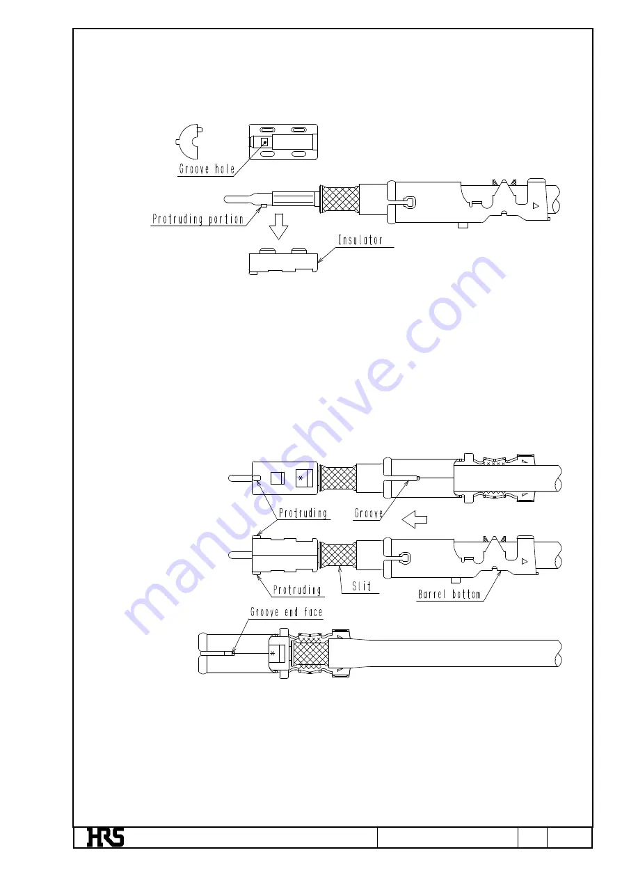
Put the above contact unit onto the insulator, and fit another insulator onto the contact unit.
Note: 1.
Put the protruding part of the center contact onto the groove hole.
Note: 2.
Pull the cable at a force of approximately 4.9N and check that the contact unit will not be
pulled out.
(7)
Assemble the outer contact to the insulator.
Note: 1.
Check that the direction of the outer contact is correct as shown in the illustration below.
Make sure that the left and right dents on the insulator coincide with the grooves of the
outer contact in coaxial direction (i.e., the slit of the outer ferrule coincide in position with
the barrel bottom of the outer contact).
Note: 2.
Insert the cable until the insulator is stopped by the groove end face of the outer contact.
Jul.1.2022 Copyright 2022 HIROSE ELECTRIC CO., LTD. All Rights Reserved.


