3. Assembly and installation procedure HIRO 160 Q
6
Before starting installation work, please check
whether the dimensions given in the lift unit drawing
agree with the actual dimensions on the installation
site.
Check against the lift unit drawing and the
production parts list to ensure that the lift unit
delivered is complete.
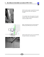
Arrange the guide rail supports according to length
and position.
Please refer to the list of supports to see which
support length is required in each case. The
position of the supports is shown in the lift unit
drawing.
All the dimensions relevant for the installation work
are shown in red on the lift unit drawing.
All dimensions on the lift unit drawing refer to the
centre of the guide rail tube.
The guide rail supports are shown as S1/S... in the
lift unit drawing and are indicated in the parts list
with their various lengths.
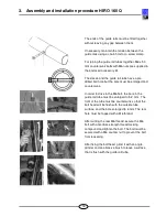
Take the fixing brackets out of the enclosed
accessories kit and take out the accompanying
screws for assembling the supports.
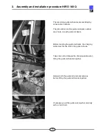
Place the guide rail supports, guide rail brackets,
clips and fixing screws on the staircase treads
specified in the lift unit drawing.


