- 8 -
■
Setup Instructions
1
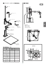
Attach Pole to Base.
Use the four Lock screws
③
to attach the Pole
Holder
②
to the Base
①
. Next, insert the Pole
④
into
the Pole Holder
②
and fix, using the two Pole Lock
screws
⑤
.
2
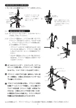
Attach the screwdriver to Holder.
2-1
When using Models VMS-40 and VMS-50
2-1-1 The holes (in the Driver Holder) to be used for
attaching the screwdriver depend on the model of
screwdriver.
Please confirm the screwdriver model to be used.
●
Applicable Screwdrivers
A
B
C
CL-2000
SS-2000
BL-2000
CL-3000/4000
SS-3000/4000
α-4500/5000
BL-3000/5000
CL-6000/6500/7000
SS-6500/7000
α-6500
2-1-2 Remove the Hanger and Driver Cord from the
screwdriver before attaching it.
2-1-3 Loosen the two Driver Lock screws
⑦
and set the
screwdriver as in the right figure so that the Switch
Lever faces the Driver Holder.
2-1-4 It requires a certain amount of force to fit the
Driver Connector into the Holder
⑥
. Pass the
Connector through the Driver Holders.
2-1-5 Align the Driver Holder Lock Screw holes and
Hanger Screw holes, then fasten the Driver Lock
screws
⑦
.
Pole
Base
Pole Lock screws
Base Lock screws
Base
Lock screws
Pole
Holder
2
Connector
Holder
L wrench
Hanger
Screw hole
Hanger
Screw holes
Driver Lock screw
(Hexagon Socket Head
Cap screw)
Driver Lock Screw
(Hexagon Socket Head
Cap screw)
Ring for PG-7000
Ring for PG-7000
Hanger Screw
holes
Lock Screw
holes
• After setting the screwdriver in step 2-1-4, fit ring
onto the connector and connect the Driver Cord.
• Align the Lock Screw holes in the Holder and the
Hanger Screw holes, then fasten the Driver Lock screws.
L wrench
C
B
A
Holder
17
8
4
Attaching CL-2000 Holder
EN
unit: mm


