background image

Appx.

15

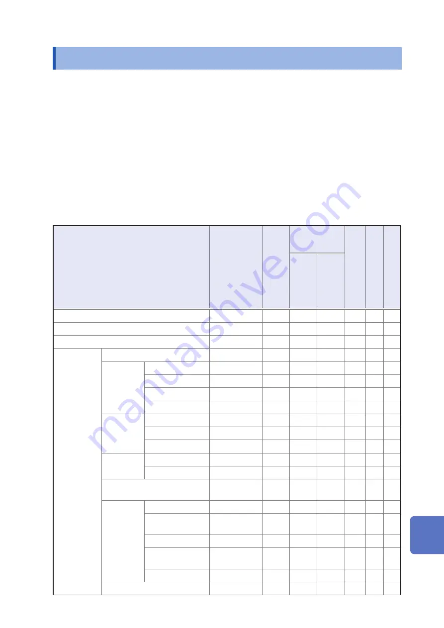
Initial Settings Table

Appx. 11 Initial Settings Table

The following table shows the initial settings of the instrument.

This following information is also included:

 •

Setting status after initialization

 •

Whether the setting reverts to its default value when the instrument is turned on

 • Whether the setting is included in panel save/load operation

 •

Whether the setting is included in file save/load operation

For more information about initialization, see the following sections:

 •System reset initiated on the 

instrument

: See "Initializing (System Reset)" (p. 228).

 •

Full reset initiated on the 

instrument

: See "Performing a full reset (If you are unable to perform a system reset)" (p. 229).

 •

Initialization initiated with a 

command (

*

RST

:PRESet

)

: See the descriptions of the 

*

RST

 and 

:PRESet

 commands in the Communications 

Command User Manual on the bundled LCR Application Disc.

Yes: Available, No: Unavailable, ←: The same as the initial setting

Setting Items

Default setting

Initialized initiated on 

instrument

Initialization 

initiated with 

command

Reverts to default value 

at power-on

Panel save/ Load

File save/ Load

*

RST

:PRESet

Measurement mode

LCR

No

Yes Yes

Measurement parameter

Z/OFF/

θ

/OFF

No

Yes Yes

Magnification display

OFF

No

No

Yes

Basic settings

Measurement frequency

1 kHz

No

Yes Yes

Measurement 

signal level

Mode

V

No

Yes Yes

V

1.000 V

No

Yes Yes

CV

1.000 V

No

Yes Yes

CC

10.00 mA

No

Yes Yes

Limit

ON/OFF

OFF

No

Yes Yes

Current limit value

100.00 mA

No

Yes Yes

Voltage limit value

5.00 V

No

Yes Yes

DC bias

ON/OFF

OFF

No

Yes Yes

Bias value

0.00 V

No

Yes Yes

Trigger mode

INT

(Internal Trigger)

No

Yes Yes

Measurement 

range

Mode

AUTO

No

Yes Yes

AUTO range control 

function

100 m

Ω

/100 M

Ω

No

Yes Yes

Range

100

Ω

No

Yes Yes

Judgment synchroni

-

zation setting

OFF

No

Yes Yes

LOW Z

OFF

No

Yes Yes

Measurement speed

MED

No

Yes Yes

10

9

8

7

6

5

4

3

2

1

Appx.

Summary of Contents for IM3536

Page 1: ...truction Manual Instruction Manual IM3536 LCR METER July 2018 Revised edition 3 IM3536A981 03 18 07H 99 Washington Street Melrose MA 02176 Phone 781 665 1400 Toll Free 1 800 517 8431 Visit us at www TestEquipmentDepot com ...

Page 2: ...97 5 1 Setting the Cable Length Cable Length Correction 98 5 2 Open Correction 99 Before performing open correction 99 All correction 100 Contents Introduction 1 Verifying Package Contents 1 Measurement process 6 Safety Information 10 Operating Precautions 12 1 Overview 17 1 1 Product Overview and Features 17 1 2 Names and Functions of Parts 18 1 3 Screen Layout and Operation 20 Screen transition ...

Page 3: ...judgment result output to EOM output and judg ment result reset operation 181 Disabling the trigger input during mea surement and setting the trigger input effective edge 182 Setting the E ________ OM output method and output time 183 Spot correction 103 5 3 Short Correction 105 Before performing open correction 105 All correction 106 Spot correction 107 5 4 If Open or Short Correction Fails to Co...

Page 4: ... 229 11 3 Error Massage and Error Display 230 11 4 Discarding the Instrument 235 Appendix Appx 1 Appx 1 Measurement Param eters and Calculation Formula Appx 1 Appx 2 Measurement of High Impedance Components Appx 3 Appx 3 Measurement of In cir cuit Components Appx 4 Appx 4 Countermeasures Against Incorporation of External Noise Appx 5 Countermeasures against incorporation of noise from the power li...

Page 5: ...ories panel switch button and connectors If damage is evident or if it fails to operate according to the specifications contact your authorized Hioki distribu tor or reseller Confirm that these contents are provided IM3536 LCR Meter 1 Accessories LCR Application Disc 1 Includes Communications Instruction Manual PDF edition ex planation of communications commands USB driver and sample programs The ...

Page 6: ...g up 9140 10 4 Terminal Probe Measurable range DC to 200 kHz Maximum applied voltage 42 V peak AC DC Maximum applied current 1 A peak AC DC Measurement terminal hole diameter 0 3 mm to 5 mm Width of the measurement sample Close the tips of the probes and place the probes so that they are as far apart as the width of the measurement sample Clamp the probes on the short bar 9500 10 4 Terminal Probe ...

Page 7: ... Maximum applied voltage DC 40 V Measurement terminal hole diameter 0 3 mm to 1 5 mm Cord length 1 m Connect the 9261 10 and the instrument with the connection cable do not clamp anything to the fixture Insert the short bar all the way into the sample mounting area 9262 Test Fixture 1 Measurable range DC to 8 MHz Maximum applied voltage DC 40 V Measurable sample dimensions Lead diameter of φ0 3 mm...

Page 8: ...sample width of 3 5 0 5 mm or less Move the knob to open the high and low electrodes use the width of the measurement sample as the open spacing Move the knob to close the high and low electrodes 9699 SMD Test Fixture 1 ショート オープン Measurable range DC to 120 MHz Maximum applied voltage 42 V peak AC DC Measurable sample dimensions Test sample width of 1 mm to 4 mm Test sample height of 1 5 mm or less...

Page 9: ...plied voltage DC 40 V Connect the following items to the 9268 10 Measurement cables and fixture or probe in the open correction state Bias application cable External DC bias power supply with the 0 V output setting on Connect the following items to the 9268 10 Measurement cables and fixture or probe in the short correction state Bias application cable External DC bias power supply with the 0 V out...

Page 10: ...ecessary before performing the correction process de scribed in Step 9 4 Set the date and time p 38 5 Connect the 9263 SMD test fixture to the measurement terminals Overview of connections p 35 The connection method varies with the probes and fixture being used For more information see each prod uct s user manual Optional probes and fixtures p 2 6 Set the measurement mode to LCR Default setting LC...

Page 11: ...hen you wish to superimpose the DC voltage on the measurement signal during capaci tance measurement LEVEL Measurement signal mode Open circuit voltage V mode Measurement signal level 1 000 V p 49 Required configure based on the measurement sample DELAY Trigger delay 0 0000 s p 64 Optional If the trigger synchronous output function is enabled set to a large enough value that measurement can stabil...

Page 12: ...05 1 5 2 3 4 2 Set the cable length for the 9263 use a setting of 0 m 3 Place the 9263 SMD Test Fixture in the open state and perform open correction 4 Place the 9263 SMD Test Fixture in the shorted state and perform short correction To save measurement conditions internally or load previously saved measurement conditions 6 Saving and Loading Measurement Condition and Correction Value Data p 123 T...

Page 13: ...y See 11 3 Error Massage and Error Display p 230 The following functionality is also available Measuring conductivity and dielectric constant p 68 Measuring at a high level of precision p 56 Limiting instability of display values p 57 Setting measurement conditions for each measurement range p 80 Increasing the measurement precision or measurement speed p 83 Detecting contact errors during two ter...

Page 14: ...iousness and the hazard levels are classified as follows DANGER Indicates an imminently hazardous situation that will result in death or serious injury to the operator WARNING Indicates a potentially hazardous situation that may result in death or serious injury to the operator CAUTION Indicates a potentially hazardous situation that may result in minor or moderate injury to the operator or damage...

Page 15: ...ement categories To ensure safe operation of measuring instruments IEC 61010 establishes safety standards for vari ous electrical environments categorized as CAT II to CAT IV and called measurement categories DANGER Using a measuring instrument in an environment designated with a higher numbered category than that for which the instrument is rated could result in a severe accident and must be care...

Page 16: ...propriate locations may cause a malfunction of instrument or may give rise to an accident Avoid the following locations Exposed to direct sunlight or high temperature Exposed to corrosive or combustible gases Exposed to a strong electromagnetic field or electrostatic charge Near induction heating systems such as high frequency induction heating sys tems and IH cooking equipment Susceptible to vibr...

Page 17: ...or Dis play p 230 before contacting your dealer or Hioki representative To avoid damage to the instrument protect it from physical shock when transporting and handling Be especially careful to avoid physical shock from dropping After use always turn OFF the power Before Turning Power On WARNING Before turning the instrument on make sure the supply voltage matches that indicated on its power connec...

Page 18: ...result in incorrect measurements due to poor connection or other reasons Before using a fixture or the like read the instruction manual supplied with the product to be used Before Using the USB Flash Drive CAUTION Do not transport the instrument while a USB flash drive is connected Damage could result Inserting a USB flash drive upside down backwards or in the wrong direction may damage the USB fl...

Page 19: ...a wire becoming dislocated and contacting another conduc tive object can be serious hazard Use screws to secure the external connec tors Ensure that devices and systems to be connected to the EXT I O terminals are properly isolated CAUTION To avoid damage to the instrument observe the following cautions Do not apply voltage or current to the EXT I O terminals that exceeds their ratings Do not shor...

Page 20: ...16 Operating Precautions ...

Page 21: ...erformed con tinuously using preconfigured measurement conditions This function enables for example making pass fail judgment with different mea surement conditions Example Performing C D measurement with 120 Hz and Rs measurement with 100 kHz in succession Various interfaces supported Supports the most suitable EXT I O handler interface for production lines USB GP IB RS 232C and LAN Comparator fu...

Page 22: ...HPOT jack Detected voltage high terminal LPOT jack Detected voltage low terminal LCUR jack Measurement current detected terminal GUARD jack Shield measurement ground terminal Power button Turns the instrument on and off while the main power switch is in the on position p 36 The main power switch is located at the rear Front USB connector Connect a USB flash drive storage device p 138 See Handling ...

Page 23: ...plication Disc Communications Manual MAC address of the LAN Bundled LCR Application Disc Communications Manual Manufacturer s serial number Shows the serial number Do not remove this label as it is required for product support LAN connector Allows you to connect the instrument to external devices using a LAN cable Bundled LCR Application Disc Communications Manual EXT I O connector Allows you to c...

Page 24: ...s used on the screen to represent this action CAUTION Do not use excessive force on the touch panel and do not use sharp objects that could damage the touch screen Screen transition diagram Continuous measurement mode Measurement screen SET screen MODE screen FILE screen Return to the Measurement screen with the EXIT key This screen is used to view continuous measurement results p 22 This screen i...

Page 25: ...ed to configure detailed settings such as measurement condi tions p 25 This screen is used to configure cor rection functionality p 27 This screen is used to configure the instrument s inter faces to set the time and date and to check the system p 28 This screen is used to check and manipu late files on the USB flash drive p 29 This screen is used to view measured values and measurement condition ...

Page 26: ...sage status of internal memory p 88 Menu keys MODE Select the measurement mode p 24 SET Set the advanced settings p 25 ADJ Set the correction p 27 LCR mode only SYS Set the system p 28 LCR mode only FILE Set the save settings p 29 Displays error mes sages p 230 Indicates the selected measurement mode Indicates the interface that is cur rently set p 132 Operation keys Displays operation keys as app...

Page 27: ...arges the display of mea sured values and comparator judgment results p 42 Switches measurement condition set tings information p 26 Saves the measurement data p 143 When the external trigger is selected activates the trigger manually p 64 How to view measured values See 3 2 Viewing Measured Values p 41 Measurement screen in continuous measurement mode Panel No Measured value Judgment result Scrol...

Page 28: ...key 2 Select the measurement mode Displays the measurement screen for the selected mode LCR LCR mode p 39 CONTINUOUS Continuous measurement mode p 93 After changing the measurement mode check all settings including correction before performing measure ment Correction values will be deleted so you will need to repeat the correction process ...

Page 29: ... the continuous measurement CONTINUOUS mode screen see 4 Using Continuous Measurement Mode p 93 1 Touch the SET key 2 Touch a tab BASIC Basic setting Rdc DC resistance measurement setting shown during LCR mode operation only ADVANCED Application settings 3 Touch the key for the parameter you wish to set The settings screen for the parameter will be displayed 4 Configure settings for LCR mode and c...

Page 30: ... displayed INFO COMP When comparator function has been set Displays information about comparator measurement judg ment standards INFO BIN When BIN function has been set Displays information about BIN measurement judgment standards You can check settings information on the Mea surement screen during LCR mode operation Current measurement conditions This information is not shown when using the zoom ...

Page 31: ... BIAS DC bias L FREQ Line frequency DC only DCR OFFSET DC adjustment value acquisition time 2 DC DELAY DC delay ADJ DELAY Adjustment delay 1 When set to ON the display will show ON if set to a measurement range or measurement frequency for which the output resistance will be 100 Ω See Low Z High Accuracy Mode p 56 2 The acquisition time will not be displayed if DC adjustment is ON When DC adjustme...

Page 32: ...nd date and to check the system LCR mode only 1 Touch the SYS key 2 Touch a tab I F Configure interface settings INFO Check the version and other system information TEST Check the system CLOCK Set the time 3 Touch the key for the parameter you wish to set The settings screen for the parameter will be displayed 4 Check the settings and version number or perform a test measurement See 7 Setting the ...

Page 33: ... and edit file relat ed settings It is displayed after the USB flash drive is inserted into the instrument s receptacle 1 Touch the FILE key 2 Touch a tab LIST Display files Load save or delete initialize files SET Configure file saving operation 3 Configure file saving settings display files and manipulate files See 8 Using USB Flash Drive Sav ing and Loading Data p 137 1 Overview ...

Page 34: ...30 Screen Layout and Operation ...

Page 35: ...ecting the Power Cord p 34 3 Connect measurement cables optional Hioki probes or test fixture to the measurement connectors p 35 Check that the instrument s power switch is turned off 4 Connect the external interface as needed For more information about making RS 232C GP IB USB and LAN connections see the Com munications Instruction Manual on the bundled LCR Application Disc External interface RS ...

Page 36: ...me and date p 38 When measuring DC resistance be sure to set the line frequency before performing measurement p 54 After allowing the instrument to warm up for at least 60 minutes perform open correction and short correction and connect the instrument to the sample p 36 ...

Page 37: ...distributor or reseller Is the insulation on a cables or is any metal exposed No Metal Exposed Metal Exposed If there is any damage measured values may be unstable and measurement errors may occur Replace the cable with an undamaged one 2 Instrument Inspection Is damage to the instrument evi dent Yes If damage is evident request repairs No When turning power on Does the Opening screen appear model...

Page 38: ...wer cord Connect the power cord to the power inlet on the instrument and plug it into an outlet 1 Check that the instrument s power is turned off 2 Connect a power cord that matches the line voltage to the power inlet on the instrument 100 V AC to 240 V AC Rear Power inlet 3 Plug the other end of the power cord into an outlet Turn off the power before disconnecting the power cord ...

Page 39: ...ls on the instru ment Points to pay attention to when making your own probe Use 50 Ω coaxial cable for the measurement cable When it ships from the factory the instrument has been adjusted for the length of its cable Since use of a cable with a different capacitance value between the coaxial cable s core wire and the shielding will introduce a measurement error use a cable whose capacitance value ...

Page 40: ...s main power switch Once the main power switch has been turned on the instru ment can be turned on and off using the power button on the front panel This feature is convenient when embedding the instrument in an automated tester or on a produc tion line If the main power switch is turned off in the suspended state the instrument will power on in the suspended state when the main power switch is ne...

Page 41: ...ded state ON the main power in the state hold down the front Standby Key 2 seconds approxi mately 2 seconds The power button s red indicator will light up What is the suspended state The instrument is turned off in the suspended state Only the circuit needed to light up the power button s indicator will operate To cancel the suspended state The instrument is in suspended state press the power butt...

Page 42: ...d based on the set date and time 1 Press the SYS key 2 Touch the CLOCK tab and set the date and time with the key Year Month Day Hour Minute Second 1 2 Settable range 00 00 00 January 1 2000 to 23 59 59 December 31 2099 3 Press the SET key to accept the setting 4 Press the EXIT key The measurement screen will be displayed ...

Page 43: ...ay Parameters You can select up to 4 of the 16 measurement parameters to display on the measurement screen These parameters are set on the measurement screen Example No 1 parameter Cs No 3 parameter D See Parameters p 40 1 Touch the No 1 parameter key 2 Touch the Cs key and then the EXIT key to accept the settings 1 2 3 Touch the No 3 parameter key 4 Touch the D key and then the EXIT key to accept...

Page 44: ...urement condition settings see 3 4 Setting Measurement Condi tions basic settings p 43 When Rdc is set as a parameter along with other parameters DC resistance is measured DC measurement after other parameters are measured using an AC signal AC measurement DC measurement is performed automatically using the following series of operations Example When the number of average iterations is 1 Change in...

Page 45: ...hown in the screenshot below are as follows Vdc Sample terminal voltage during DC measurement 777 4 mV Idc Current flowing to sample during DC measurement 155 8 µA Vac Sample terminal voltage during AC measurement 978 3 mV Iac Current flowing to sample during AC measurement 198 1 µA For more detailed information about the screen layout see Viewing measured values Measurement screen p 22 Monitor va...

Page 46: ... ZOOM ON key Magnification Display Screen Normal measurement To cancel the zoom display Touch the ZOOM OFF key Comparator measurement BIN measurement Indicates the position of the measurement value relative to the comparator thresholds with a bar The bars will not be displayed unless both upper and lower limit values have been set If the instrument is turned off while using the zoom display the zo...

Page 47: ...tional default value OFF Optional default value OFF p 57 To limit variability of displayed values set to ON Limit Optional default value OFF p 59 To limit the voltage or current that is applied to the sample set to ON DC bias Optional default value OFF p 60 To superimpose a DC voltage on the measurement signal during measurement set to ON DC adjust Optional default value OFF p 61 To reduce measure...

Page 48: ... measured values to vary for some sam ples Screen display method For more information see p 24 Measurement screen SET key SET screen BASIC tab FREQ key 1 Enter each digit of the frequency with the buttons You can also set the value with the numeric keypad 1 2 Settable range 4 Hz to 8 MHz Set the decimal point and unit with the 10 and 1 10 keys 10 Sets the measurement frequency to 10 1 10 Sets the ...

Page 49: ... turned off The selection of ranges that can be set during AC measurement varies with the measurement frequency DC bias on off setting and cable length setting For more information see p 211 of 10 6 Measurement Range and Accuracy The guaranteed accuracy range varies depending on the measurement conditions Check the accuracy assured ranges in Guaranteed accuracy measurement level range p 213 The ra...

Page 50: ...ge limit function allows you to limit the AUTO ranging range 1 Touch the MIN key 2 Select the AUTO range lower limit range 3 Touch the EXIT key The display will return to the screen shown in step 1 4 Touch the MAX key and select the AUTO range upper limit range 5 Touch the EXIT key twice Displays the measurement screen The AUTO range scope is the selection of ranges within which the AUTO range is ...

Page 51: ...nt range setting If OVER FLOW UNDER FLOW is indicated as the measured value measurement cannot be performed with the current measurement range Change the measurement range or change to the AUTO setting so that the instrument can select an optimal range automatically The measurement range is set based on the total impedance of the sample and measurement cable Consequently you may not be able to per...

Page 52: ...nt will automatically switch to the optimal range If no judgment stan dard has been set the instrument will function the same as when the AUTO setting is enabled If only the θ D or Q measurement parameter has been set the instrument will function the same as when the AUTO setting is enabled During AC measurement because the phase angle cannot be calculated for some combina tions of parameters the ...

Page 53: ... of the voltage between the terminals of the object under test is set Constant current CC mode The value of the current flowing through the object under test is set Selecting constant voltage or constant current mode will result in longer measurement times due to the use of software feedback control For some samples changing the measurement signal level setting will cause measured values to vary C...

Page 54: ... 4 Hz to 1 0000 MHz 0 01 mA to 50 00 mA 1 0001 MHz to 8 MHz 0 01 mA to 10 00 mA 3 Touch the EXIT key twice Displays the measurement screen When low Z high accuracy mode p 56 is on the valid setting range will vary Measurement signal mode Settable range V CV 0 010 V to 1 000 V CC When the output im pedance is 10 Ω 0 01 mA to 100 00 mA When the output im pedance is 100 Ω 0 01 mA to 10 00 mA See For ...

Page 55: ...erformed Change the constant voltage value to a value that is less than or equal to the value displayed for Vac Example Constant voltage measurable range when measuring a C value of 1 µF at 10 kHz The sample impedance Zm is as follows Zm Rm jXm 0 Ω j15 9 Ω Xm 1 2πfC The impedance Zm as seen from the instrument s voltage generator is as follows Zm Ro Zm 100 Ω j15 9 Ω Ro Output resistance 100 Ω Acco...

Page 56: ...ows Zm Ro Zm 100 Ω j6 28 Ω Ro Output resistance 100 Ω Accordingly the current Im across both leads of the sample is as follows Im Vo Zm Vo 100 2 Ω Vo generator output Since the instrument s voltage generator output range is 10 mV to 5 V as per the above table the con stant voltage measurable range is Im 0 10 mA to 49 9 mA based on the above formula When low Z high accuracy mode is enabled the outp...

Page 57: ...value or select constant voltage CV and set a voltage value across these terminals Measurement sample Constant voltage CV mode operation When the sample s impedance is higher than the previous measurement a voltage that is greater than the set voltage level will be applied and this may damage the sample This is due to the fact that the output voltage is controlled and the set voltage level applied...

Page 58: ... SET screen Rdc tab LINE FREQ key 1 Select the line frequency 50 Hz Sets the line frequency to 50 Hz 60 Hz Sets the line frequency to 60 Hz 2 Touch the EXIT key twice Displays the measurement screen To suppress noise the instrument needs to be set to match the frequency of the power source Before operating set the instrument to the frequency of your commercial power If the supply frequency is not ...

Page 59: ...urement speed Measurement speed Measurement time Measurement accuracy FAST Short Low MED SLOW SLOW2 Long High 2 Touch the EXIT key twice Displays the measurement screen Measurement time varies with the measurement conditions See 10 7 About Measurement Times and Measurement Speed p 217 The waveform averaging function allows you to set the measurement speed at a higher level of detail The measuremen...

Page 60: ...high accuracy mode the measure ment signal level setting range changes p 51 Changing the low Z high accuracy mode setting while open correction short correc tion or load correction is enabled causes the correction values to be disabled Low Z high accuracy mode can only be enabled while using the 100 mΩ 1 Ω or 10 Ω range See the table below Measurement range DC measure ment AC measurement measureme...

Page 61: ...gger Average over the number of averaging times based on trigger input DC measurement Averaging processing during DC measurement calculated an arithmetic average regardless of the trigger setting Screen display method For more information see p 24 AC measurement Measurement screen SET key SET screen BASIC tab AVG key DC measurement Measurement screen SET key SET screen Rdc tab AVG key 1 Use key to...

Page 62: ...asured values at output 1 Moving average M1 M2 M3 M4 4 M4 M1 M2 M3 3 M3 M1 M2 2 M2 M1 1 M1 M5 M6 M7 M8 4 M8 M4 M5 M6 M7 4 M7 M3 M4 M5 M6 4 M6 M2 M3 M4 M5 4 M5 M6 M7 M8 M9 4 M9 M7 M8 M9 M10 4 M10 Measurement points Measurement value output Elapsed time 2 Arithmetic mean M1 M2 M3 M4 4 M4 M3 M2 M1 M5 M6 M7 M8 4 M8 M7 M6 M5 M9 M10 Measurement points Measurement value output Elapsed time ...

Page 63: ...imit Screen display method For more information see p 24 Measurement screen SET key SET screen BASIC tab LIMIT key 1 Touch the ON key Example screen When the measurement signal mode is V or CV 2 Use the key to enter the limit value You can check the voltage and current between the sample terminals using monitor values Moni tor values differ depending on the measurement signal mode setting V CV CC ...

Page 64: ...rim pose with the keys Settable range 0 V to 2 5 V If you make a mistake touch the C key and reenter the value 3 Touch the EXIT key twice Displays the measurement screen If low Z high accuracy mode p 56 is en abled the valid setting range will differ 0 V to 1 0 V The DC bias function is specifically for capacitor measurement If it is used for resistor inductor and other elements with low DC resist...

Page 65: ...ent DC measurement switching DC resistance value acquisition DC adjustment off With n average iterations Disabling DC adjustment may cause the measurement error to increase When using the instrument with DC adjustment disabled acquire the adjustment value with the sample or a circuit with equivalent DC resistance Rdc connected Because the adjustment value will vary when the sample s Rdc or ambient...

Page 66: ...ched Touching the GET DCR OFFSET key again before the trigger signal is received will cancel offset measurement When the CALIB signal is input from an external device to the EXT I O connector p 162 When the DCResistance ADJust DEMand interface communications command is sent from an ex ternal device If the parameter has not been set to Rdc the GET DCR OFFSET key will be disabled DC delay setting th...

Page 67: ...delay time required until the DC signal level stabilizes Trigger perform measurements with user defined timing Common Trigger functionality allows you to start and stop recording based on a particular signal When recording is started or stopped by a specific signal we say the trigger is gapplied or trig gering occurs With this instrument you can select the following two types of trigger Internal T...

Page 68: ...trigger signal to measurement can be set With this function it is possible to ensure that testing is started after the connection condition of the object being tested and the test cables has stabilized The setting applies to both AC and DC measurement See Trigger delay and Trigger synchronous output p 65 For more information about trigger delay timing see the figures in Measurement and data acquis...

Page 69: ... delay time between output of the measurement signal and data acquisition See 10 7 About Measurement Times and Measurement Speed p 217 When the trigger synchronous output function is set to ON the set level may be output momentarily if a measurement condition is changed The measurement signal is output when the trigger signal is input and stops after measurement ends When the contact check p 86 ti...

Page 70: ...synchronization on DC adjustment on Trigger signal DC measurement trigger synchronization on DC adjustment off DC delay Data acquisition Trigger delay Trigger delay Trigger delay DC measurement after AC measurement trigger synchronization on DC adjustment on DC measurement after AC measurement trigger synchronization on DC adjustment off Data acquisition Switching time 3 5ms Data acquisition Adjus...

Page 71: ...delay Trigger delay Trigger delay Trigger delay Data acquisition Switching time 3 5 ms DC delay Data acquisition DC measurement after AC measurement trigger synchronization off DC adjustment off Trigger delay Trigger delay Time from trigger to start of measurement 0 0 ms to 9 9999 s Trigger synchronization delay Time from signal generation to data acquisition 1 0 ms to 9 9999 s DC delay Time from ...

Page 72: ...al Screen display method For more information see p 24 Measurement screen SET key SET screen ADVANCED tab σε key 1 Select the capacitance to use when cal culating the dielectric constant Cs Series equivalent circuit mode ca pacitance F Cp Parallel equivalent circuit mode ca pacitance F 2 Touch the LENGTH key 3 Enter the length of the measurement sample and touch the ENTER key 1 2 Settable range 0 ...

Page 73: ...reference values up to 10 and the measurement values Judgment by comparator measurement and BIN measurement is performed for the No 1 param eter and No 3 parameter Therefore set the measurement values you want to judge for the No 1 parameter and No 3 pa rameter in advance See 3 1 Setting Display Parameters p 39 Comparator measurement Judgment Target Result Display No 1 parameter No 2 parameter No ...

Page 74: ...ction settings judging measurement re sults based on one judgment standard The comparator function allows you to do the following Preset a reference value and upper and lower limit values as the judgment reference and display a judgment result as HI higher than the upper limit value IN within the range set for the upper and lower limit values or LO lower than the lower limit value Output the judgm...

Page 75: ...nus sign is required for the percentage setting value reference value reference value 100 Percentage set value Upper limit comparison value Lower limit comparison value 2 The following equation is used to calculate the value Δ reference value measurement value reference value 100 The comparator and BIN judgment is made in the following order Judgment order State Judgment display 1 When the measure...

Page 76: ...ad 2 1 103 Step the units up 1 103 Step the units down Units a f p n µ m none k M G Settable range 9 99999 G to 9 99999 G If you do not wish to set an upper limit value touch the OFF key 4 Touch the ENTER key to confirm the up per limit value The display will return to the screen shown in step 2 5 Touch the LO key set the lower limit value with the numeric keypad and touch the ENTER key Settable r...

Page 77: ...and set the upper limit value with the numeric keypad 2 1 Settable range 999 999 to 999 999 Set the upper limit value as a percentage relative to the reference value If you do not wish to set an upper limit value touch the OFF key 6 Touch the ENTER key to confirm the up per limit value The display will return to the screen shown in step 2 7 Touch the LO key set the lower limit value with the numer...

Page 78: ...e or lower limit comparison value that is less than the refer ence value give the percent setting a negative sign Upper limit comparison value reference value reference value 100 Percentage set value Lower limit comparison value reference value reference value 100 Percentage set value Deviation percent setting The measurement values are displayed in deviations Δ from the reference value The follow...

Page 79: ...ment When BIN is not set OUT OF BINS When does not match any BIN Measurement screen About BIN measurement Bin measurement is performed using a process such as the example shown below Judgment BIN number No 1 Parameter No 3 Parameter BIN Judgment results Judgment Judgment Judgment Judgment Judgment Judgment Judgment Judgment The instrument will display the first BIN number for which the measurement...

Page 80: ...d comparison lower limit value In the case of the comparison lower limit value if a value that is lower than the reference value is set the minus sign is required for the percentage setting value reference value reference value 100 Percentage set value Upper limit comparison value Lower limit comparison value 2 The following equation is used to calculate the value Δ reference value measurement val...

Page 81: ...mit value with the nu meric keypad Settable range 9 99999 G to 9 99999 G When you do not want to set the upper and lower limit values touch the OFF key 7 Touch the ENTER key to confirm the up per limit value The display will return to the screen shown in step 5 8 Touch the LO key for the No 1 parameter set the lower limit value with the numeric keypad and then touch the ENTER key Settable range 9 ...

Page 82: ...ng on the measurement parameter 3 Touch the key persentage setting or key deviation percentage setting 4 Touch the REF key and enter the refer ence value with the numeric keypad 2 1 Settable range 9 99999 G to 9 99999 G 5 Touch the ENTER key to confirm the ref erence value 6 Touch the EXIT key 7 Use the key to select the BIN num ber to set and touch EDIT key 1 2 8 Touch the HI key for the No 1 par...

Page 83: ...ouch the LO key for the No 1 parameter set the lower limit value with the numeric keypad and then touch the ENTER key Settable range 999 999 to 999 999 The display will return to the screen shown in step 8 12 Using the same procedure set the up per and lower limit values for the No 3 parameter 13 Touch the EXIT key twice Displays the measurement screen The set reference value and upper and lower l...

Page 84: ...plies to both AC and DC measurement Trigger synchronous delay applies to both AC and DC measurement Measurement conditions for DC measurement Rdc Allows you to set the DC measurement speed and averaging function for individual measurement ranges 1 Turn on the range synchronization function Screen display method For more information see p 24 Measurement screen SET key SET screen ADVANCED tab RNG SY...

Page 85: ... off Touch EXIT to return to the previous screen 2 Select the setting you wish to configure Setting measurement conditions on a single screen p 82 3 Set the conditions and touch the SET key SPEED Sets the measurement speed p 55 AVG Configures averaging p 57 DELAY Sets the trigger delay p 64 BASIC tab screen only SYNC Configures the trigger synchronous out put p 65 BASIC tab screen only Touch the C...

Page 86: ... To configure settings for an individual measurement range set to OFF Touch the EXIT key to re turn to the previous screen 2 Set conditions SPEED Set measurement speed p 55 AVERAGE Configures averaging p 57 DELAY Sets the trigger delay p 64 BASIC tab screen only SYNC Configures the trigger synchro nous output p 65 BASIC tab screen only 3 Touch the SET key to accept the set tings Touch the CANCEL k...

Page 87: ...e information see p 24 Measurement screen SET key SET screen ADVANCED tab WAVE NUM key 1 Touch the ON key 2 Select the frequency band for which you wish to change the number of measure ment waveforms with the key and touch the EDIT key 1 2 Reverts to the number of measurement waveforms for each measurement speed 3 Select the number of measurement waveforms with key and touch the EXIT key 2 1 For m...

Page 88: ...z 1 to 2400 18 200 01 kHz to 300 00 kHz 1 to 960 19 300 01 kHz to 400 00 kHz 1 to 1600 20 400 01 kHz to 500 00 kHz 1 to 1600 21 500 01 kHz to 700 00 MHz 1 to 2400 22 700 01 kHz to 1 0000 MHz 1 to 2400 23 1 0001 MHz to 1 4000 MHz 1 to 960 24 1 4001 MHz to 2 0000 MHz 1 to 960 25 2 0001 MHz to 3 0000 MHz 1 to 1440 26 3 0001 MHz to 4 0000 MHz 1 to 2400 27 4 0001 MHz to 5 0000 MHz 1 to 2400 28 5 0001 M...

Page 89: ...ment range and the judgment reference value as shown below Judgment reference Nominal value of current measurement range Judgment reference value Example Current measurement range nominal value 10 kΩ Judgment reference value 150 Judgment reference 10 kΩ 1 50 15 kΩ Screen display method For more information see p 24 Measurement screen SET key SET screen ADVANCED tab Hi Z key 1 Touch the ON key 2 Us...

Page 90: ... as the contact check timing causes the trigger synchronous output function p 65 to be automatically turned on 2 Set the contact check threshold with the key Settable range 1 to 5 Threshold SENS Permissible contact resistance Ω 1 Approx 1000 2 Approx 500 3 Approx 100 4 Approx 50 5 Approx 20 3 Set only when the contact check func tion does not operate correctly Set the contact check delay time with...

Page 91: ...o disable the memory function use the keys to set the number of measurement results 1 2 Settable range 1 to 32000 The number of measurement results can only be set when the memory function is set to OFF 2 Touch the IN key or ON key Measured values in the instrument s memory are deleted once they have been saved to the USB flash drive The measure ment values are saved to the MEMORY folder in the US...

Page 92: ...ror has been displayed p 233 Number of effective digits of the measurement value You can set the number of effective digits of the measurement value for each parameter Screen display method For more information see p 24 Measurement screen SET key SET screen ADVANCED tab DIGIT key 1 Use the key to set the number of display digits For each parameter Settable range 3 to 6 2 Touch the EXIT key twice D...

Page 93: ...tinuous measurement mode p 96 Screen display method For more information see p 24 Measurement screen SET key SET screen ADVANCED tab DISP key 1 Touch the OFF key or ON key OFF Turns OFF the LCD The LCD turns off after approxi mately 10 seconds elapse since the touch panel was last touched ON Sets the LCD to always on 2 Touch the EXIT key twice Displays the measurement screen When you want to turn ...

Page 94: ... IN a beep sound is emitted NG When the comparator result is LO or HI a beep sound is emitted When judgment performed with 2 comparators IN When both of these comparator results are IN a beep sound is emitted NG When either one is LO or HI a beep sound is emitted KEY Beep sound setting for when key pressed OFF When a key is pressed no beep sound is emitted ON When a key is pressed a beep sound is ...

Page 95: ... key when the key lock setting is ON 1 2 2 Use the numerical keypad to enter the passcode and touch the ENTER key Settable range 1 to 4 digits Initial passcode 3536 If a passcode is set it needs to be entered to disable the key lock Take care not to forget the set passcode 2 Touch the EXIT key twice Displays the measurement screen The key lock is disabled from the time the EXIT key is touched unti...

Page 96: ... disabling of the key lock touch the CANCEL key If the error indication shown below check the following items Cause Remedy The UNLOCK key was touched before you entered the pass code Touch the C key and enter the passcode The entered pass code is incorrect Touch the C key and enter the passcode again If you forget the passcode perform a full reset to restore the instrument to the factory default s...

Page 97: ...s measurement set which panels to use Save the measurement conditions with the panel save function in advance See 6 1 Saving Measurement Conditions and Correction Values Panel Save Function p 124 Screen display method For more information see p 24 Measurement screen SET key SET screen BASIC tab A list of the measurement conditions saved appears Any panel for which only the compensation value ADJ w...

Page 98: ...ment Results Measurement results can be checked on the measurement screen If another screen is being dis played touch the EXIT key Measured values for the selected No 1 parameter and No 3 parameter will be displayed Measrement screen Panel No No 1 parameter measured value Measurement results Comparator measurement Displays judgment results for the No 1 and No 3 parameters BIN measurement Displays ...

Page 99: ...measurement is performed If it is set to AFTER to give priority to the measurement time the screen update time becomes short This is because the screen is updated once after all measurements are complete The default setting is REAL Screen display method For more information see p 24 Measurement screen SET key SET screen ADVANCED tab DRAW key 1 Touch the AFTER key REAL Updates the screen after meas...

Page 100: ...reby reducing power consumption The default setting is ON i e the LCD display remains on continuously This setting is linked to the auto off setting for LCD mode p 89 Screen display method For more information see p 24 Measurement screen SET key SET screen ADVANCED tab DISP key 1 Touch the OFF key OFF The LCD turns off after approximately 10 seconds elapse since the touch panel was last touched ON...

Page 101: ...urement cables probes or fixtures You will be unable to obtain correct values if measurement is performed in the correction state prior to replace ment When performing correction make sure that there is no noise source nearby Noise may cause an error when performing correction ex Servo Motor switching power source high voltage cable and etc Perform correction under conditions that are similar to t...

Page 102: ...e 1 m Select this when the cable length is 1 m 2 m Select this when the cable length is 2 m 4 m Select this when the cable length is 4 m 2 Touch the EXIT key twice Displays the measurement screen If the cable length changes repeat open short and load correction The guaranteed accuracy range varies with the cable length See E Coefficient of the measurement cable s length p 215 When manufacturing yo...

Page 103: ...Length Cable Length Correction p 98 3 Arrange the measurement cables probes and fixtures as they will be when measurement will actually be performed Changing the configuration of them may result in correction not being performed properly For more information about how to connect the instrument see 2 4 Connecting the Measurement Cables Probes or Fixture p 35 4 Adjust the distance between the HI and...

Page 104: ...in Step 2 of the process and the open correction value will remain unchanged The correc tion range can be limited See p 101 Correction will start Correction value acquisition time Approx 50 seconds Touch when you wish to cancel correction The display will return to the screen shown in step 2 and the open correction value will remain unchanged The next screen will be displayed once cor rection has ...

Page 105: ... nu meric keypad 1 2 Settable range 4 Hz to 8 MHz default setting 4 Hz If you make a mistake touch the C key to reenter the value Touch the MIN key to return to the previous screen without changing the settings 4 Press a unit key to confirm the setting The frequency is not confirmed until a unit key is pressed If you attempt to set a measurement fre quency greater than 8 MHz it will automati cally...

Page 106: ...minimum correction frequency the maximum and minimum correction frequen cies will be switched automatically If the default settings are being used the instru ment will display MINIMUM and MAXIMUM 7 Touch the EXEC key Correction will be performed Please wait for the process to complete 8 Touch the EXIT key twice Displays the measurement screen ...

Page 107: ... frequency to correct with the numeric keypad and touch the SET key to accept the setting 1 2 The previous value will be displayed until you enter a value Settable range DC 4 Hz to 8 MHz The maximum frequency varies with the cable length p 215 Touch the C key to cancel input If you attempt to set a measurement fre quency greater than the maximum fre quency for each cable length setting it will aut...

Page 108: ...he measurement fre quency and the number of points The next screen will be displayed once cor rection has completed normally Correction results Conductance susceptance Correction No Measurement frequency You can check the conductance and sus ceptance for each correction point with the keys Correction can be performed for imped ances of at least 1 kΩ If the impedance in the open state is less than ...

Page 109: ...asurement cable probe or fixture being used p 2 to p 5 For more information review the appropriate user manual Necessary item Shorting bar This shorting bar is for short circuit ing together the ends of the test leads Use an object whose imped ance is as low as possible If you use a metallic wire or the like as a shorting bar try to ensure that it is as thick and short as pos sible OK Shorting met...

Page 110: ...e will remain unchanged The correction range can be limited p 101 Correction starts Compensation value acquisition time Approx 50 seconds Touch when you wish to cancel correction The display will return to the screen shown in step 2 and the short correction value will remain unchanged The next screen will be displayed once cor rection has completed normally Correction results Effective resistance ...

Page 111: ...d touch the SET key to confirm it 1 2 Until one of these keys is pressed for input of a numerical value the previous frequency for which Spot correction was performed is displayed Settable range DC 4 Hz to 8 MHz The maximum frequency varies with the cable length p 215 Touch the C key to cancel input If you attempt to set a measurement fre quency greater than the maximum fre quency for each cable l...

Page 112: ... and number of points The next screen will be displayed once cor rection has completed normally Correction results Effective resistance reactance Correction No Measurement frequency You can check the effective resistance and reactance for each correction point with the keys The valid correction range for impedance is 1 kΩ or less Correction cannot be performed if the measured value cable or fixtur...

Page 113: ...t may not be possible to perform correction at high frequencies Verify that the sample is not connected Correction cannot be performed while the sample is being measured Check the correction range limitation function p 101 and the DC bias unit When DC cor rection is on DC correction cannot be performed while the DC bias unit is connected Verify contact between LPOT and LCUR and between HPOT and HC...

Page 114: ...d Adjusting To change the cable length setting touch the CANCEL key Completed Touching the EXIT key will enable the ac quired correction value Solution Verify that the length of the connected cable and the cable length setting mach p 98 The connected cable length is detected based on the voltage monitor value It may not be possible to properly detect the cable length depending on the cable type an...

Page 115: ...orrection Measurement screen ADJ key ADJ screen OPEN key To disable short correction Measurement screen ADJ key ADJ screen SHORT key 1 Touch the ADJUST key 2 Touch the OFF key and then touch the EXIT key 1 2 3 Touch the EXIT key twice Displays the measurement screen The correction values that are stored internally are not cleared by the operation described above When ALL or SPOT is selected the st...

Page 116: ... of the measurement signal mode to correct 4 DC bias DC BIAS p 117 Enable or disable DC bias and set the value 5 Parameter type MODE p 117 Set the parameter to use as the reference value 6 Reference value 1 REF1 p 118 Set the Z Cs Cp Ls Lp Rs reference value selected for the parameter type 7 Reference value 2 REF2 p 118 Set the θ D Rs Rp Q X reference value selected for the parameter type Resets t...

Page 117: ...asurement conditions as the load correction conditions After touching the GET key touch the SET key to accept the settings Touch to cancel con figuration of the cor rection conditions The display will return to the screen shown in step 3 and the correction con ditions will remain unchanged You cannot skip ahead in the order of settings Correction cannot be performed if all set tings have not been ...

Page 118: ...nditions when correction is performed Use of different conditions will prevent load correction from being performed If the current measurement frequency and correction frequency do not match an error such as the follow ing will be displayed on the measurement screen If the current measurement conditions and correction conditions other than correction frequency do not match correction will be perfo...

Page 119: ... closed Settable range DC 4 Hz to 8 MHz The maximum frequency varies with the cable length p 215 If you make a mistake touch the C key to reenter the value 3 Touch the EXIT key The dialog box will be closed Selecting the correction range 1 Touch the RANGE key 2 Select the range for correction Touch when you wish to enable LOW Z op eration 3 Touch the EXIT key The dialog box will be closed The sele...

Page 120: ...e 4 Touch the EXIT key The dialog box will be closed Since load correction when the frequency is set to DC is fixed to 1 V in open voltage V mode the correc tion signal level cannot be set LOW Z Range V CV OFF All range 1 V fixed ON All range 1 V fixed Valid voltage level and current level setting range load correction during AC measurement V CV LOW Z Range V CV OFF All range 4 Hz to 1 0000 MHz 0 ...

Page 121: ...or the compensation frequency setting the DC bias setting cannot be set Selecting the parameters to use as reference values 1 Touch the MODE key 2 Select the parameter mode of the refer ence value to be set 3 Touch the EXIT key The dialog box will be closed See Parameters p 40 When DC is selected for the correction frequency setting DC measurement Rdc is selected automati cally and the parameter t...

Page 122: ... accept the setting 2 Uses a multiple of 1 Touching EXIT without touching a unit key will also cause a multiple of 1 to be used Touch when you wish to cancel input This dialog box will be closed 1 Settable range Same as the maximum display range for the selected parameter See 10 1 General Specifications p 187 If you make a mistake touch the C key to reenter the value 3 Touch the EXIT key The dialo...

Page 123: ...LOAD key 1 Select the correction condition number to reset with the keys and then touch the EDIT key 2 1 2 Touch the RESET key and then touch the SET key Touch when you wish to cancel the reset This dialog box will be closed 1 2 3 Touch the EXIT key twice Displays the measurement screen When load correction fails to complete normally If correction fails a window like the following appears Touch EX...

Page 124: ...can disable correction by setting the correction setting to OFF Screen display method For more information see p 27 Measurement screen ADJ key ADJ screen LOAD key 1 Touch the ADJUST key 2 Touch the OFF key and then touch the EXIT key 1 2 3 Touch the EXIT key twice Displays the measurement screen ...

Page 125: ...rrection value of θ A integration value of the measured value X B the value added to measured value X Screen display method For more information see p 27 Measurement screen ADJ key ADJ screen SCALE key 1 Touch the ON key and then touch the EXIT key 1 2 When you wish to cancel scaling Touch OFF 2 Select the correction coefficient of the parameter you want to change The parameters and correction coe...

Page 126: ... the C key 7 Touch the SET key 8 Touch the EXIT key Displays the measurement screen If you select the same parameter multiple times and set a different correction coefficient for each scaling will be performed using the correction coefficient for the parameter with the lowest number The correction coefficients of the other parameter numbers become invalid Example In the case of the following setti...

Page 127: ...ved as panel No 1 Correction values have been saved as panel No 3 Measurement conditions have been saved as panel No 5 First set the measurement mode to LCR mode p 24 Settings can be configured on the SET screen Panel save function p 124 Saves measurement conditions and correction values as a panel Panel load function p 128 Loads a panel Editing panel data Changes the panel name p 129 Deletes the ...

Page 128: ...NCED tab PANEL key 1 Touch the SAVE TYPE key 2 Select the type of data to save and touch the EXIT key 1 2 ALL Saves all HARD and ADJ content Indication on screen LCR ADJ HARD Saves the measurement condition and cable length correction setting value Indication on screen LCR ADJ Saves only each of the setting values and correction values of open correc tion short correction load correction and corre...

Page 129: ...9 60 ADJ correction values 0 to 63 64 to 127 128 Information In order from left Measurement parameters Judgment mode PARA1 PARA2 PARA3 PARA4 COMP or BIN Indicates that nothing is saved Mode Type of saved data Notation Meaning LCR ADJ All LCR and ADJ content LCR LCR measurement conditions and cable length correction setting value ADJ Only each of the setting values and correction values of open cor...

Page 130: ...27 Touch when you wish to cancel the save operation Panel number display range No 001 to No 128 See PANEL screen layout p 125 2 To change the panel name If you do not wish to change the panel name proceed to step 5 Touch the RENAME key Cancels the save operation and displays the PANEL screen 3 Enter the panel name with the numeric keypad and touch the PANEL NAME key Changes the key board type Dele...

Page 131: ... Touch the OVER WRITE key Touch when you wish to cancel the save overwrite operation 6 Touch the EXIT key twice Displays the measurement screen When you touch the VIEW key VIEW dialog box Allows you to view the contents of the previous and next dialog boxes Closes the VIEW dialog box 6 Saving and Loading Measurement Condition and Correction Value Data ...

Page 132: ... see p 24 Measurement screen SET key SET screen ADVANCED tab PANEL key 1 Select the panel number to load with the keys and then touch the LOAD key 1 2 Touch when you wish to check the contents of saved panels See p 127 Touch when you wish to cancel the load operation Panel number display range No 001 to No 128 See PANEL screen layout p 125 2 Touch the LOAD key Cancels the load operation and closes...

Page 133: ...TION key 1 2 Touch when you wish to check the information of the selected panel p 127 Touch when you wish to cancel the operation to change the panel name 2 Touch the RENAME key 3 Enter a panel name with the numeric keypad and touch the PANEL RENAME key Changes the key board type Deletes the last character Deletes all input characters Cancels to change the panel name and closes the dialog box Up t...

Page 134: ...nd then touch the OPTION key 1 2 Touch when you wish to check the information of the selected panel p 127 Touch when you wish to cancel the operation to delete the panel 2 Touch the DELETE key The DELETE dialog box will be displayed You will be able to check some of the con tents saved in the panel 3 Touch the DELETE key Touch when you wish to cancel the delete operation The dialog box will be clo...

Page 135: ...S 232C or LAN inter face Checking the instrument s version p 132 Allows you to check the instrument s version and other infor mation Serial number version MAC address USB ID and interfaces Testing the system Self diagnosis p 133 Allows you to check the instrument s screen internal memory and EXT I O status Panel test Panel calibration Testing the screen display status and LED status ROM RAM test T...

Page 136: ...face you wish to config ure 2 Configure the selected interface USB RS 232C GP IB and LAN settings Refer to the Communications Instruction Manual on the bundled LCR Application Disc 3 Touch the EXIT key Displays the measurement screen 7 2 Checking the Version of the Instrument This section describes how to check the instrument s serial number version MAC address USB ID and interfaces Screen display...

Page 137: ...s you to verify that output signals are output normally from EXT I O and that input signals can be read properly Panel test Allows you to check for touch panel errors Screen display method For more information see p 28 Measurement screen SYS key SYS screen TEST tab TOUCH SCREEN TEST key 1 Touch the key displayed of the screen If the pressed keys are highlighted and the green appears the touch pane...

Page 138: ...ws you to check the screen display status and LED status Screen display method For more information see p 28 Measurement screen SYS key SYS screen TEST tab DISPLAY LED TEST key 1 Touch the screen and check for switch ing on and off of screen colors and the LEDs on the front of the instrument The screen and LED status should change each time you touch the screen Front panel LEDs Screen color All li...

Page 139: ...isplays the measurement screen Testing EXT I O input output signals Allows you to verify that output signals are output normally from EXT I O and that input signals can be read properly Screen display method For more information see p 28 Measurement screen SYS key SYS screen TEST tab I O HANDLER TEST key 1 To perform an output signal test Touch the button with the name of the signal for which you ...

Page 140: ...136 Testing the System Self diagnosis ...

Page 141: ... 155 Other Allows you to format initialize a USB flash drive p 140 Allows you to check the contents of files on a USB flash drive p 157 Allows you to delete files and folders from a USB flash drive p 158 This section describes how to create a folder on a USB flash drive p 159 Allows you to check the usage rate and file system of the USB flash drive p 160 File format The following files can be hand...

Page 142: ...ve is not recognized try using another USB flash drive Removing a USB flash drive Check that the USB flash drive is not being accessed saving read ing etc by the instrument and then remove it No remove operation needs to be performed on the instrument Screen Display when Using USB When a USB flash drive has been recognized properly the USB flash drive icon is displayed at the top of the measuremen...

Page 143: ...e sorting order by touching the FILE NAME DATE or SIZE Ascending order Descending order File size File save date and time File format FDR folder CSV text data CSV format BMP screen copy data SET instrument set tings data PNL panel data File name Information of the USB flash drive Allows you to confirm details by touching this information p 160 Recognizing the USB flash drive blue USB is being acce...

Page 144: ...wish to cancel the format operation The dialog box will be closed Formatting of the USB flash drive will be gin No operation is possible during formatting When formatting ends the dialog is closed When you perform a format all of the data saved to the USB flash drive is deleted and cannot be restored Carefully check the contents before you perform a format We recommend making a backup of any impor...

Page 145: ... measurement values displayed in the current screen in CSV format Continuous measurement mode Saves the measurement result of each panel in CSV format Saves all measurement conditions and measurement data for each panel in a single file Measurement results are saved in the following order measuring instrument information time and date measurement conditions measurement parameters and measurement v...

Page 146: ...SHORT OFF LOAD OFF CABLE 0 m SCALE OFF Z ohm OFF PHASE deg OFF 4 983329E 03 0 074 Instrument information Time and date Measurement conditions Measurement parameters Measurement values see below Header Quotation mark Delimiter How to interpret measured values Example No 1 parameter Z impedance Ω No 2 parameter OFF No 3 parameter θ impedance phase angle No 4 parameter OFF 4 983329E 03 0 074 No 1 par...

Page 147: ...hether to use the save measurement parameters as the header p 146 DELIM Sets the delimiter type p 148 QUOTE Sets the quotation mark character p 149 5 Touch the EXIT key Displays the measurement screen 6 Touch the SAVE key The measurement data will be saved Touching SAVE automatically creates a folder on the USB flash drive and saves the file there The date is used for the name of the folder create...

Page 148: ...r the OFF key do not save as the header 2 Touch the EXIT key The dialog box will be closed When ON When OFF HIOKI E E CORPORATION IM3536 Ver 1 00 Serial No 123456789 DATE 11 11 30 TIME 10 10 06 FREQ 1 0000E 03 Hz V 1 000 V LIMIT OFF RANGE AUTO 10k ohm Display when ON Save date November 30 2011 save time 10 10 06 HIOKI E E CORPORATION IM3536 Ver 1 00 Serial No 123456789 FREQ 1 0000E 03 Hz V 1 000 V...

Page 149: ... OPEN OFF SHORT OFF LOAD OFF CABLE 0 m SCALE OFF Z ohm OFF PHASE deg OFF 4 983329E 03 0 074 HIOKI E E CORPORATION IM3536 Ver 1 00 Serial No 123456789 DATE 11 11 30 TIME 10 10 06 Z ohm OFF PHASE deg OFF 4 983329E 03 0 074 Display when ON Measurement frequency 1 0000 kHz measurement signal mode V measurement signal level 1 000 V current limit OFF measurement range AUTO 10 kΩ low Z high accuracy mode...

Page 150: ... ohm LOW Z OFF JUDGE SYNC OFF JUDGE OFF SPEED MED TRIG INT AVG OFF DELAY 0 0000 s TRIG SYNC OFF DCBIAS OFF OPEN OFF SHORT OFF LOAD OFF CABLE 0 m SCALE OFF Z ohm OFF PHASE deg OFF 4 983329E 03 0 074 HIOKI E E CORPORATION IM3536 Ver 1 00 Serial No 123456789 DATE 11 11 30 TIME 10 10 06 FREQ 1 0000E 03 Hz V 1 000 V LIMIT OFF RANGE AUTO 10k ohm LOW Z OFF JUDGE SYNC OFF JUDGE OFF SPEED MED TRIG INT AVG ...

Page 151: ... series resistance RS ohm Rp Effective resistance Ω Equivalent parallel resistance RP ohm Cs Capacitance F Equivalent series capacitance CS F Cp Capacitance F Equivalent parallel capacitance CP F D Loss factor tanδ D G Conductance S G S X Reactance Ω X ohm Ls Inductance H Equivalent series inductance LS H Lp Inductance H Equivalent parallel inductance LP H Q Q factor Q B Susceptance S B S OFF No d...

Page 152: ...GE SYNC OFF JUDGE OFF SPEED MED TRIG INT AVG OFF HIOKI E E CORPORATION IM3536 Ver 1 00 Serial No 123456789 DATE 11 11 30 TIME 10 11 36 FREQ 1 0000E 03 Hz V 1 000 V LIMIT OFF RANGE AUTO 10k ohm LOW Z OFF JUDGE SYNC OFF JUDGE OFF SPEED MED TRIG INT AVG OFF When semicolon When space HIOKI E E CORPORATION IM3536 Ver 1 00 Serial No 123456789 DATE 11 11 30 TIME 10 11 42 FREQ 1 0000E 03 Hz V 1 000 V LIMI...

Page 153: ...ATE 11 11 30 TIME 10 12 05 FREQ 1 0000E 03 Hz V 1 000 V LIMIT OFF RANGE AUTO 10k ohm LOW Z OFF JUDGE SYNC OFF JUDGE OFF SPEED MED TRIG INT AVG OFF HIOKI E E CORPORATION IM3536 Ver 1 00 Serial No 123456789 DATE 11 11 30 TIME 10 10 06 FREQ 1 0000E 03 Hz V 1 000 V LIMIT OFF RANGE AUTO 10k ohm LOW Z OFF JUDGE SYNC OFF JUDGE OFF SPEED MED TRIG INT AVG OFF When single quotation mark HIOKI E E CORPORATIO...

Page 154: ...ent Data Saving a copy of the screen Allows you to save the screen currently displayed to the USB flash drive in bmp file format 256 colors or monochrome 2 colors The file extension is bmp BMP file sample Color Monochrome ...

Page 155: ...ochrome 2 color BMP file 4 Touch the EXIT key twice Displays the measurement screen 5 Touch the SAVE key A copy of the measurement screen will be saved When the SAVE key is pressed a folder is automatically created in the USB flash drive and the file is saved The date is used for the name of the folder created when you press SAVE key Example Saved on September 30 2014 20140930 To specify the save ...

Page 156: ...ave the data 4 Select the folder in which you wish to save data with the keys and then touch the SET key Touch to cancel the configuration process The dialog box will be closed 1 2 5 Touch the EXIT key Displays the measurement screen The following folders can be specified The root directory of the USB flash drive The folder name is all single byte characters A folder name containing Japanese or ot...

Page 157: ...uch the SAVE key Touch when you wish to cancel the save operation The dialog box will be closed Touch when you wish to change the filename of the setting file A filename entry dialog box will be displayed The measurement data is saved 4 Touch the EXIT key Displays the measurement screen Touching the SAVE key will cause a SETTING folder to be automatically created on the USB flash drive and setting...

Page 158: ...h the SAVE key Touch when you wish to cancel the save operation The dialog box will be closed Touch when you wish to change the folder name of the setting file A folder name entry dialog box will be displayed Settings data including panels will be saved 5 Touch the EXIT key Displays the measurement screen Touching the SAVE key will cause a SETTING folder to be automatically created on the USB flas...

Page 159: ...he setting file SET or panel file PNL to load with the keys and touch the LOAD key 1 2 Touch when you wish to check the contents of a file See p 157 4 Touch the LOAD key Touch when you wish to cancel the load op eration The dialog box will be closed The file will be loaded and applied as the current settings 5 Touch the EXIT key Displays the measurement screen If a load error is displayed If an er...

Page 160: ...eys and touch the SELECT key 1 2 3 Using the keys select the folder which settings were saved with the all save function and touch the SELECT key 1 2 4 Using the keys select the file which TYPE is ALL and touch the ALL LOAD key 1 2 5 Touch the LOAD key When you want to cancel loading touch this key The dialog box will be closed All files saved in the folder will be loaded and applied as the curren...

Page 161: ...rmation see p 29 Measurement screen FILE key FILE screen LIST tab 1 Insert the USB flash drive into the front USB connector p 138 2 Select a file with the keys and touch the VIEW key 1 2 If the selected file is a folder FDR the SE LECT key will be displayed Touching this key will display the files in the folder The file s contents will be displayed CSV file BMP file SET file PNL file 3 Touch the E...

Page 162: ...38 2 Select the file or folder you wish to delete with the keys and touch the OPTION key 1 2 3 Touch the DELETE key 2 4 Touch the DELETE key Touch when you wish to cancel the delete op eration The dialog box will be closed The selected file or folder will be deleted A deleted file or folder cannot be re stored once it is deleted 5 Touch the EXIT key Displays the measurement screen If the folder to...

Page 163: ...into the front USB connector p 138 2 Touch the OPTION key 3 Touch the FOLDER key 2 Enter the save name Up to 12 characters Changes the keyboard type Deletes the last character Deletes all input characters 4 Touch the CREATE FOLDER key Touch when you wish to cancel the creation operation The dialog box will be closed The folder is created 5 Touch the EXIT key Displays the measurement screen 8 Using...

Page 164: ...ay method For more information see p 29 Measurement screen FILE key FILE screen LIST tab 1 Insert the USB flash drive into the front USB connector p 138 2 Touch the part indicating the disc infor mation File system File system type All Total size Used Space used Avail Space free 3 Touch the EXIT key The dialog box will be closed 4 Touch the EXIT key Displays the measurement screen ...

Page 165: ...ystem See p 162 to p 179 Confirm input and output ratings understand the safety precautions for connecting a control system and use accordingly Control system Signal output destination or signal input source 2 Configuring the instrument See p 180 To input a signal from the external device to the instrument to start and stop measure ment external trigger p 63 To output contact errors during 2 termi...

Page 166: ... EXT I O connector and supports use of the following types of connectors Instrument side connector 37 pin D sub female with 4 40 screws Mating connectors DC 37P ULR solder type DCSP JB37PR pressure weld type Japan Aviation Electronics Industry Ltd Instrument connector signal assignments Signal assignments vary with the measurement mode Signal logic is 0 V to 0 9 V for LO level and 5 V to 24 V for ...

Page 167: ... LO Generates output when the comparator judgment result is LO for the No 1 parameter D1 2 BCD output signal 13 2 OUT BIN5 Generates output when the BIN measurement result is BIN5 Negative Level PARA3 IN Generates output when the comparator judgment result is IN for the No 3 parameter D2 0 BCD output signal 14 2 OUT BIN7 Generates output when the BIN measurement result is BIN7 Negative Level AND O...

Page 168: ... is BIN2 Negative Level PARA1 IN Generates output when the comparator judgment result is IN for the No 1 parameter D1 1 BCD output signal 31 2 OUT BIN4 Generates output when the BIN measurement result is BIN4 Negative Level PARA3 HI Generates output when the comparator judgment result is HI for the No 3 parameter D1 3 BCD output signal 32 2 OUT BIN6 Generates output when the BIN measurement result...

Page 169: ...signal ground 10 OUT ERR Outputs when a sampling error overcurrent error contact error High Z reject error constant voltage constant cur rent error or voltage current limit value exceeded error occurs Negative Level 11 OUT No 1_PARA1 HI Outputs HI comparator judgment results for the first No 1 parameter Negative Level 12 OUT No 1_PARA1 LO Outputs LO comparator judgment results for the first No 1 p...

Page 170: ...the sample may be changed Falling Edge 30 OUT No 1_PARA1 IN Outputs IN comparator judgment results for the first No 1 parameter Negative Level 31 OUT No 1_PARA3 HI Outputs HI comparator judgment results for the first No 3 parameter Negative Level 32 OUT No 1_PARA3 LO Outputs LO comparator judgment results for the first No 3 parameter Negative Level 33 OUT No 2_PARA1 HI Outputs HI comparator judgme...

Page 171: ...ry value to LD0 to LD6 Example OFF HI 5 V to 24 V ON LO 0 V to 0 9 V Pin No LD6 LD5 LD4 LD3 LD2 LD1 LD0 Panel 1 OFF OFF OFF OFF OFF OFF ON Panel 2 OFF OFF OFF OFF OFF ON OFF Panel 3 OFF OFF OFF OFF OFF ON ON Panel 4 OFF OFF OFF OFF ON OFF OFF Panel 5 OFF OFF OFF OFF ON OFF ON Panel 6 OFF OFF OFF OFF ON ON Panel 7 OFF OFF OFF OFF ON ON ON Panel 8 OFF OFF OFF ON OFF OFF OFF Panel 32 OFF ON OFF OFF O...

Page 172: ...data No 1 digit data Polarity ERR Signal correspondence table Dm 3 Dm 2 Dm 1 Dm 0 Measured value OFF OFF OFF OFF 0 OFF OFF OFF ON 1 OFF OFF ON OFF 2 OFF OFF ON ON 3 OFF ON OFF OFF 4 OFF ON OFF ON 5 OFF ON ON OFF 6 OFF ON ON ON 7 ON OFF OFF OFF 8 ON OFF OFF ON 9 m 4 to 1 Output Description Polarity OFF OFF OFF OFF Plus OFF OFF OFF ON Minus ERR OFF OFF OFF OFF Normal data OFF OFF OFF ON OVERFLOW OFF...

Page 173: ...FF 12 345 Decimal point 99 9999 C1 D4 D3 D2 D1 3 2 1 0 3 2 1 0 3 2 1 0 3 2 1 0 OFF High order Decimal display 1 2 3 4 BCD output OFF OFF OFF ON OFF OFF ON OFF OFF OFF ON ON OFF ON OFF OFF ON Low order Decimal display 5 0 Polarity 1 ERR 0 BCD out put OFF ON OFF ON OFF OFF OFF OFF OFF OFF OFF ON OFF OFF OFF OFF NC Contact error C1 D4 D3 D2 D1 3 2 1 0 3 2 1 0 3 2 1 0 3 2 1 0 OFF High order Decimal di...

Page 174: ...fter measurement H side contact error after measurement Simultaneous H and L contact errors before measurement L side contact error before measurement H side contact error before measurement Underflow HI Pin Nos 12 and 32 LO 2 3 LCR mode only Overflow Pin Nos 11 and 31 LO 2 4 LCR mode only Outside of High Z reject limit range LO Normal judgment Normal judgment Normal judgment Normal judgment Const...

Page 175: ...iming examples the valid edge of the TRIG signal is set to falling DOWN Reset TRIG Start of measurement signal INDEX EOM CALIB LD_VALID LD0 LD6 ERR PARA x x BINx Judgment result Judgment result JUDGE RESET ON JUDGE RESET OFF t7 t8 t3 t4 t5 t1 t2 t6 Analog end of measurement signal End of measurement signal Comparator and BIN result output Last judgment result Last judgment result Panel number Pane...

Page 176: ...lay trigger delay and DC delay times are added to t3 When using the External trigger p 218 condition 500 µs is added to t3 4 Reference value for Measurement frequency 1 kHz Measurement speed FAST Range HOLD p 217 Because the speed with which the comparator and BIN judgment results rise LO HI varies with the architecture of the circuit connected to EXT I O using the judgment results level immediate...

Page 177: ...ng the pulse width for which LO on EOM is held Setting on the instrument See Setting the EOM output method and output time p 183 Setting with a communications command See LCR Application Disc Communications Command IO EOM PULSe Start of measurement signal Analog end of measurement signal When HOLD Analog end of measurement signal When PULSE End of measurement signal When HOLD End of measurement si...

Page 178: ...e Measurement in progress Measurement complete received EOM D1 0toD4 0 EOM wait No 1 parameter BCD low order digit Setup start C1 ON C2 OFF Setup time 0 2ms max Wait D1 0toD4 0 No 3 parameter BCD high order digit Specification C1 OFF C2 ON Setup time 0 2ms max No 3 parameter BCD high order digit Acquisition D1 0toD4 0 Wait C1 ON C2 ON Setup time 0 2ms max D1 0toD4 0 Wait No 1 parameter Specificati...

Page 179: ...ates the absence of signal input or output ON HI OFF LO 1 No x_PARAy HI No x_PARAy IN No x_PARAy LO AND 2 Reset when signal changes to EOM HI measurement in progress ON Do not reset when signal changes to EOM HI measurement in progress Last judgment result remains Signal line Description INDEX EOM For both INDEX and EOM a transition to Hi off is performed when the first panel mea surement starts a...

Page 180: ...electrical specifications and example connections for the instrument Circuit diagrams Input circuit Internally Isolated 5 V 8 ISO_5 V Internally Isolated Common Signal Ground 2kΩ 1kΩ PLC etc Output Common 22 27 ISO_COM 9 ISO_COM IM3536 1 4 5 6 21 23 24 26 Do not connect external power 25 20 ...

Page 181: ... not connect external power PLC etc Input Common Zener Voltage 30 V Internally Isolated 5 V 8 ISO_5 V 27 ISO_COM 9 ISO_COM Internally Isolated Common Signal Ground IM3536 37 16 13 14 15 17 33 10 11 12 19 28 29 30 31 32 34 35 36 9 External Control ...

Page 182: ...Isolated by photo couplers Nch open drain output current sink active low Maximum load voltage 30 V Maximum output current 50 mA ch Residual voltage 1 V or less 50 mA Internally isolated power supply Output voltage 4 5 V to 5 0 V Maximum output current 100 mA External power input none Connection examples Input circuit connection examples IM3536 IM3536 IM3536 IM3536 Input Switch connections Input Re...

Page 183: ...Negative logic output ISO_COM Output Output Wired or 30 V max 50 mA max IM3536 IM3536 Iutput Common PLC PLC Connection to programmable controller plus common input Connection to programmable controller negative common input ISO_COM Output 30 V max IM3536 ISO_COM Output 30 V max IM3536 ISO_COM ISO_COM Output Output IM3536 IM3536 9 External Control ...

Page 184: ...same time as the measurement start signal Setting on the instrument See p 181 See LCR application dikc Communications command IO RESult RESet Enabling trigger input for during measurement Whether to enable or disable trigger input from the EXT I O during measurement during EOM HI can be selected on the instrument or by a communication command Setting on the instrument See p 182 See LCR application...

Page 185: ...urement is in progress See 9 2 Example Measurement Timing Timing Charts p 171 Screen display method For more information see p 24 Measurement screen SET key SET screen ADVANCED tab IO JUDGE key 1 Set the delay time with the key Settable range 0 0000 s to 0 9999 s If you make a mistake touch the C key to reenter the value 2 Select the judgment result hold reset setting OFF Stores the last judgment ...

Page 186: ...e or falling edge as the valid edge of trigger input from the EXT I O 9 2 Example Measurement Timing Timing Charts p 171 Screen display method For more information see p 24 Measurement screen SET key SET screen ADVANCED tab IO TRIG key 1 Select the I O trigger function setting OFF Disables trigger input from the EXT I O during measurement ON Enables trigger input from the EXT I O during measuremen...

Page 187: ... ADVANCED tab IO EOM key 1 Select the EOM output method HOLD EOM will be in the HI state for analog measurement time calculation time delay time t1 see 9 2 Example Measurement Timing Timing Charts p 171 PULSE EOM will be in the HI state except during the set pulse width time 1 2 2 Set the EOM output time during PULSE operation with the keys Settable range 0 0001 s to 0 9999 s If you make a mistake...

Page 188: ...to judgment mode Judgment results will be output ON Sets the output mode to BCD mode Measured values will be output 2 Set the decimal point position with the keys PARA1 Sets the decimal point position for the No 1 parameter PARA3 Sets the decimal point position for the No 3 parameter Select 9 99999G 999 999M 99 9999M 9 99999M 999 999k 99 9999k 9 99999k 999 999 99 9999 9 99999 999 999m 99 9999m 9 9...

Page 189: ...e ERR signal will be output in the following circumstances When sampling error When contact error When High Z reject error When constant voltage constant current error When voltage current limit value exceeded error See Output signals when errors occur p 170 Is a connector or flat cable for connection provided A connector and cable are not supplied so you need to pro vide them yourself Is direct c...

Page 190: ...2C LAN interfaces To enable communication the communication conditions need to be set on the instrument For details on the communication condition settings refer to Setting the Interface Controlling the Instrument from a Computer p 132 For more detailed information about control methods see the Communications Instruction Manual on the bundled LCR Application Disc ...

Page 191: ...e θ Phase angle Cs Equivalent series capacitance Rs Equivalent series resistance ESR Cp Equivalent parallel capacitance Rp Equivalent parallel resistance Q Q factor X Reactance D Loss coefficient tanδ G Conductance Rdc DC resistance B Susceptance σ Conductivity ε Permittivity Display range Parameters Display range 6 digits Z 0 00 m to 9 99999 GΩ Y 0 000 n to 9 99999 GS θ 0 000 to 180 000 Rs Rp X R...

Page 192: ...tor voltage accuracy specifications and software control range 1 10 mV Default setting 1 000 V default mode V mode Constant current CC mode Setting range Normal mode 4 Hz to 1 0000 MHz 10 µA to 50 mA maximum 5 V 1 0001 MHz to 8 MHz 10 µA to 10 mA maximum 1 V Low Z high accuracy mode When the output resistance is 100 Ω 10 µA to 10 mA maximum 1 V When the output resistance is 10 Ω 10 µA to 100 mA ma...

Page 193: ...tor current accuracy specifications and software control range 1 10 mV Default setting OFF Output impedance HCUR terminal measurement frequency 1 kHz Normal mode 100 Ω 10 Ω Low impedance high accu racy mode 10 Ω 2 Ω The output resistance and termination resistance will be set to 50 Ω The output resistance is the resistance connected to the HCUR terminal and the termination resistance is the resist...

Page 194: ...zation OFF Range Guaranteed accuracy range AUTO ranging range 100 MΩ 8 MΩ to 200 MΩ 8 MΩ or more 10 MΩ 800 kΩ to 100 MΩ 800 kΩ to 10 MΩ 1 MΩ 80 kΩ to 10 MΩ 80 kΩ to 1 MΩ 100 kΩ 8 kΩ to 1 MΩ 8 kΩ to 100 kΩ 10 kΩ 800 Ω to 100 kΩ 800 Ω to 10 kΩ 1 kΩ 80 Ω to 10 kΩ 80 Ω to 1 kΩ 100 Ω 8 Ω to 100 Ω 8 Ω to 100 Ω 10 Ω 800 mΩ to 10 Ω 800 mΩ to 10 Ω 1 Ω 80 mΩ to 1 Ω 80 mΩ to 1 Ω 100 mΩ 1 mΩ to 100 mΩ 0 Ω to ...

Page 195: ...Residual charge protection function Function Protects the instrument from discharge voltage in the event that it is con nected to a charged capacitor Discharge voltage reference value At 400 V DC or less 5 J or less at 1 000 V DC or less 0 5 J or less The energy W J stored in capacitance C F at voltage V V can be deter mined using the following equation See Appx 6 The Residual Charge Protection Fu...

Page 196: ...Voltage fluctuations of 10 from the rated supply voltage are taken into account Rated power supply fre quency 50 Hz 60 Hz Maximum rated power 50 VA Dimensions Approx 330W 119H 230D mm 12 99 W 4 69 H 9 06 D excluding protrusions Mass Approx 4 2 kg 148 1 oz Standards EMC EN61326 Class A Safety EN61010 Effect of radiated radio frequency electromagnetic field Z 5 rdg θ 5 at 10 V m Effect of conducted ...

Page 197: ... delay time value acquisition will be performed auto matically when the delay time is changed Touch the GET DCR OFFSET key on the screen Input a signal from an external device to the instrument s EXT I O connector Send a communications command from an external device to the instru ment s interface Default setting ON DC delay Function Sets the time until DC resistance measurement starts Setting ran...

Page 198: ...e OFF Trigger delay Function Sets the delay time from trigger input to measurement Setting range 0 0000 s to 9 9999 s 0 0001 s resolution Default setting 0 0000 s Trigger synchronous output Function Outputs the measurement signal after trigger input and applies it to the sample during measurement only Allows you to set a wait time until data is acquired Operation mode OFF ON Setting range 0 0010 s...

Page 199: ... external device from EXT I O Judgment method Set as absolute values Set the upper and lower limits for the measurement parameters as abso lute values Set as percentage Enter the reference value and set the upper and lower limits as percentag es of the reference value Measured values for the measurement param eters will be displayed as they are Set as deviation percentage Enter the reference value...

Page 200: ...f OPEN state during 2 terminal measurement Function When the measurement value is higher than the judgment reference a con tact error is output Judgment reference Can be set to 0 to 30000 1 resolution of range full scale Error output Displays errors on the measurement screen Outputs errors to an external device from the EXT I O connector Default setting OFF Memory Function Measurement result items...

Page 201: ... it ON Keeps the LCD display on at all times Default setting ON Key lock Function Protects settings by disabling all setting changes except cancellation of key lock Allows you to set a passcode for use when canceling key lock Operation mode OFF ON Valid passcode setting range 1 to 4 digits default setting 3536 Default setting OFF Magnification display Function The display of measurement values and...

Page 202: ...0 1 0001 kHz to 2 0000 kHz 1 to 600 1 8 40 600 2 0001 kHz to 3 0000 kHz 1 to 1200 2 12 60 1200 3 0001 kHz to 5 0000 kHz 1 to 2000 3 20 100 2000 5 0001 kHz to 10 000 kHz 1 to 3000 5 40 200 3000 10 001 kHz to 20 000 kHz 1 to 1200 2 16 80 1200 20 001 kHz to 30 000 kHz 1 to 480 1 6 24 480 30 001 kHz to 50 000 kHz 1 to 800 1 10 40 800 50 001 kHz to 100 00 kHz 1 to 1200 2 16 80 1200 100 01 kHz to 140 00...

Page 203: ...h panel Touching the touch panel after it goes out will reenable it ON Keeps the LCD display on at all times Judgment results output Allows you to output up to two sets of judgment results simultaneously from the instrument s EXT I O Correction Open correction Increases measurement precision by eliminating the effects of the mea surement cable s stray admittance All correction Function Acquires co...

Page 204: ...Z before correction Z correction coefficient θ θ before correction θ correction value Z correction coefficient Z reference value accutual data of Z θ correction value θ reference value accutual data of θ Operation mode OFF ON Default setting OFF Cable length correction Function Corrects measurement errors caused by the effects of the measurement cable Cable length settings 0 m 1 m 2 m 4 m Default ...

Page 205: ...FF IN NG Default setting NG OFF Does not sound a beep for comparator judgments IN Sounds a beep when the result is an IN judgment NG Sounds a beep when the result is LO or HI Key input setting OFF ON Default setting ON OFF Does not sound a beep when a key is touched ON Sounds a beep when a key is touched Tone setting Allows you to select any of four beep tones A B C or D Default setting A Internal...

Page 206: ...screen File name Generated automatically based on the time and date and given the exten sion SET for setting files panel save extension is PNL External control using the EXT I O connector Input and output signals Function Switches between judgment mode and BCD mode In BCD mode comparator BIN judgment results are not output BCD output is only enabled in LCR mode BCD output includes the No 1 and No ...

Page 207: ...it to the HI state Valid setting range 0 0001 s to 0 9999 s Default setting HOLD 0 0050 s Delay setting from judgment result output to EOM output Function Allows you to set the delay time for EOM LO output from judgment result output Valid setting range 0 0000 s to 0 9999 s Default setting 0 0000 s Resetting judgment results Function Allows you to set whether to reset the judgment results after EO...

Page 208: ...the serial number Version information Displays the software version and the FPGA version MAC address Displays the MAC address USB ID Displays the USB ID Self check function Panel test Allows you to check for touch panel errors Panel calibration Allows you to calibrate the touch panel Display status test Allows you to check the screen display status and LED status ROM RAM test Allows you to check t...

Page 209: ...up ply Voltage 4 5 V to 5 V Maximum output current 100 mA Floating relative to protective ground potential and measurement circuit Pin and signal assignments See Instrument connector signal assignments p 162 Rear USB connector Connector USB Type B receptacle Electrical specifications USB2 0 High Speed Number of receptacles 1 Front USB connector Connector USB type A Electrical specification USB2 0 ...

Page 210: ...l Hardware Software Terminator CR LF CR Communication speed 9600 bps 19200 bps 38400 bps 57600 bps GP IB connector Connector 24 pin Centronics type connector Standards IEEE 488 1 1987 IEEE 488 2 1987 LAN connector Connector RJ 45 connector Transmission method 10Base T 100Base T automatic detection Protocol TCP IP ...

Page 211: ...z 2 fm is measurement frequency MHz Basic accuracy chart Range For DC measurement For AC measurement measurement frequency 4 Hz to 99 99 Hz 100 00 Hz to 999 99 Hz 1 0000 kHz to 10 000 kHz 100 MΩ A 1 B 1 A 6 B 5 A 3 B 2 A 3 B 2 A 5 B 3 A 2 B 2 A 2 B 2 10 MΩ A 0 5 B 0 3 A 0 8 B 1 A 0 5 B 0 3 A 0 5 B 0 3 A 0 8 B 0 5 A 0 4 B 0 2 A 0 4 B 0 2 1 MΩ A 0 2 B 0 1 A 0 4 B 0 08 A 0 3 B 0 05 A 0 3 B 0 05 A 0 3...

Page 212: ...B 0 5 A 0 2 B 0 02 A 1 B 0 3 A 2 B 0 3 10 kΩ A 0 3 B 0 02 A 0 5 B 0 05 A 2 B 0 5 A 0 2 B 0 02 A 0 5 B 0 05 A 1 5 B 0 3 1 kΩ A 0 2 B 0 02 A 0 4 B 0 02 A 1 5 B 0 2 A 0 15 B 0 02 A 0 4 B 0 02 A 1 5 B 0 2 100 Ω A 0 2 B 0 02 A 0 5 B 0 03 A 1 5 B 0 2 A 0 15 B 0 02 A 0 5 B 0 03 A 1 5 B 0 2 10 Ω A 0 4 B 0 05 A 0 8 B 0 1 A 2 B 1 5 A 0 3 B 0 03 A 0 5 B 0 05 A 2 B 1 1 Ω A 1 B 0 3 A 1 5 B 1 A 3 B 3 A 0 5 B 0 ...

Page 213: ...asurement range is used and the 1 0000 kHz to 10 000 kHz column since the measurement frequency is 10 kHz in the Basic accuracy p 207 2 Calculate the basic accuracy for Z using the Z coefficients A and B Based on the accuracy table coefficient A 0 2 and coefficient B 0 02 Plug in the values for the 100 Ω range in the Basic accuracy p 207 into the follow ing equation Z accuracy 100 0 2 0 02 1 50 Ω ...

Page 214: ...ow ing equation Z accuracy 10 10 144 0 05 0 02 1 10 k k Ω Ω 0 05 rdg 4 Similarly calculate the basic accuracy of θ The accuracy table yields the values A 0 03 and B 0 02 Using the basic accuracy formula of Basic accuracy p 207 for 1 k or more θ accuracy 10 10 144 0 03 0 02 1 10 k k Ω Ω 0 03 5 Calculate the range within which Z and θ values can be acquired from the basic accuracy 0 05 min 1 0144 1 ...

Page 215: ... MΩ 10 MΩ Not available 1 MΩ 100 kΩ Available 10 kΩ 1 kΩ 100 Ω 10 Ω 1 Ω 100 mΩ Not available Unavailable when DC bias is ON but may be set when DC bias is OFF Cable length 1 m Range Measurement frquency DC 4 Hz to 99 99 Hz 100 Hz to 999 99 Hz 1 kHz to 10 kHz 10 001 kHz to 100 kHz 100 01 kHz to 1 MHz 1 0001 MHz to 5 MHz 5 0001 MHz to 8 MHz 100 MΩ 10 MΩ Not available 1 MΩ 100 kΩ 10 kΩ Available 1 kΩ...

Page 216: ...Hz 100 MΩ 10 MΩ 1 MΩ 100 kΩ Not avail able 10 kΩ Available 1 kΩ 100 Ω 10 Ω 1 Ω 100 mΩ Unavailable when DC bias is ON but may be set when DC bias is OFF Cable length 4 m Range Measurement frequency DC 4 Hz to 99 99 Hz 100 Hz to 999 99 Hz 1 kHz to 10 kHz 10 001 kHz to 100 kHz 100 01 kHz to 1 MHz 1 0001 MHz to 5 MHz 5 0001 MHz to 8 MHz 100 MΩ 10 MΩ 1 MΩ 100 kΩ Available Not available 10 kΩ 1 kΩ 100 Ω...

Page 217: ...1 V to 5 V 0 501 V to 5 V 8 kΩ to 100 kΩ 0 010 V to 5 V 0 050 V to 5 V 0 101 V to 1 V 10 kΩ 10 kΩ to 100 kΩ 0 010 V to 5 V 0 050 V to 5 V 0 101 V to 1 V 800 Ω to 10 kΩ 0 010 V to 5 V 0 050 V to 5 V 0 050 V to 1 V 0 101 V to 1 V 1 kΩ 1 kΩ to 10 kΩ 0 010 V to 5 V 0 050 V to 5 V 0 050 V to 1 V 0 101 V to 1 V 80 Ω to 1 kΩ 0 010 V to 5 V 0 050 V to 1 V 0 101 V to 1 V 100 Ω 8 Ω to 100 Ω 0 010 V to 5 V 0...

Page 218: ... 99 100 to 599 600 to 2499 2400 No Frequency band Measurement speed coefficient 16 8 4 2 1 2 4 00 Hz to 10 00 Hz 1 2 3 4 3 10 01 Hz to 39 99 Hz 1 2 to 4 5 to 9 10 4 40 00 Hz to 99 99 Hz 1 2 to 4 5 to 39 40 5 100 00 Hz to 300 00 Hz 1 2 to 4 5 to 49 50 6 300 01 Hz to 500 00 Hz 1 2 to 9 10 to 199 200 7 500 01 Hz to 1 0000 kHz 1 to 4 5 to 19 20 to 299 300 8 1 0001 kHz to 2 0000 kHz 1 to 7 8 to 39 40 t...

Page 219: ... 160 to 2399 2400 28 5 0001 MHz to 6 0000 MHz 1 to 7 8 to 63 64 to 249 250 to 3999 4000 29 6 0001 MHz to 8 0000 MHz 1 to 7 8 to 63 64 to 249 250 to 3999 4000 E Coefficient of the measurement cable s length The coefficient of the measurement cable s length is shown in the table below Measurement cable s length 0 m 1 m 2 m 4 m Coefficient 1 1 5 2 3 The settable range for frequency varies with the me...

Page 220: ... 0 0 1 10 100 1k 10k 100k 1M 10M 1 10 100 1k 10k 100k 1M 10M Measurement frequency Hz L H 100m 10m 1m 100u 10u 1u 100n 10n 1n 100p Measurable range for C 0 0 0 0 0 0 0 0 0 0 0 0 0 0 1 10 100 1 10 100 1k 10k 100k 1M 10M C F Measurement frequency Hz 100m 10m 1m 100u 10u 1u 100n 10n 1n 100p 10p 1p 100f 1f ...

Page 221: ...f 600 Tf 12000 Tf 30 001 kHz to 50 000 kHz 25 Tf 250 Tf 1000 Tf 20000 Tf 50 001 kHz to 100 00 kHz 50 Tf 400 Tf 2000 Tf 30000 Tf 100 01 kHz to 140 00 kHz 100 Tf 800 Tf 4000 Tf 60000 Tf 140 01 kHz to 200 00 kHz 100 Tf 800 Tf 4000 Tf 60000 Tf 200 01 kHz to 300 00 kHz 250 Tf 1500 Tf 6000 Tf 120000 Tf 300 01 kHz to 400 00 kHz 250 Tf 2500 Tf 10000 Tf 200000 Tf 400 01 kHz to 500 00 kHz 250 Tf 2500 Tf 100...

Page 222: ...0 µs 100 mΩ 1 Ω ON 0 01 to 1 V DC all frequency OFF 500 µs 10 Ω OFF 0 01 to 1 V DC 4 Hz to 1 MHz OFF 500 µs Measurement times E ________ OM Measurement times I ____________ NDEX A B C D E A Calculation time no OPEN SHORT LOAD correction HOLD range no screen display normal measurement Measurement speed Calculation time FAST All frequencies 0 5 ms MED SLOW SLOW2 Times are given for measurement while...

Page 223: ...001 MHz to 2 0000 MHz 2 0001 MHz to 8 0000 MHz 2 When the measurement range or low Z high accuracy mode is changed When changing the measurement range or switching low Z high accuracy mode on or off a wait of 4 ms is added 3 When the measurement signal level is changed When changing the AC measurement signal level a 4 ms wait is added 4 When the DC bias is changed A 1 5 ms wait is inserted when sw...

Page 224: ...220 About Measurement Times and Measurement Speed ...

Page 225: ... Lifetimes The characteristics of some of the parts used in the product may deteriorate with extended use To ensure the product can be used over the long term it is recommended to replace these parts on a periodic basis When replacing parts please contact your Hioki distributor The service life of parts varies with the operating environment and frequency of use Parts are not guaranteed to operate ...

Page 226: ...rtation is not covered by the warranty When sending the instrument for repair be sure to include details of the problem Cleaning To clean the instrument wipe it gently with a soft cloth moistened with water or mild detergent IMPORTANT Never use solvents such as benzene alcohol acetone ether ketones thinners or gasoline as they can deform and discolor the case Wipe the LCD display gently with a sof...

Page 227: ...instrument is in the key lock state Disable the key lock See Key lock function Disabling key opera tion p 91 The instrument is being con trolled by an external device us ing the communications cable Cancel remote mode A key other than the pressed one is pressed Panel correction has not been performed Perform panel calibration Panel calibration p 134 Nothing is displayed on the screen The instrumen...

Page 228: ...el range p 213 Measurement frequency AC p 44 and Measurement signal level AC p 49 The instrument is being used in an environment with a large amount of noise If you are using the instrument in a high noise environment consider taking the following mea sures Use guarding See Appx 2 Measurement of High Impedance Components p Appx 3 Implement anti external noise measures See Appx 4 Countermeasures Ag...

Page 229: ...than lower limit error See 11 3 Error Massage and Error Display p 230 If the range is not appropriate Change to an appropriate range or perform measurement using auto ranging It is neces sary to set both the AC measurement and DC measurement ranges See Measurement range AC DC p 45 If there is a break or short in the wiring Check the wiring and perform measurement with the correct wiring connection...

Page 230: ... See 5 2 Open Correction p 99 and 5 3 Short Correction p 105 Load correction has been en abled Set the load correction off See 5 6 Load Correction Correcting Values to Match Reference Values p 112 The delay time from connection of the sample to measurement is not long enough Ensure there is an appropriate trigger delay and trigger synchronous output wait time See Trigger perform measurements with ...

Page 231: ...Failure to do so will result in a transmission error on the measuring instrument and the transmission error tone will continue to sound in the event of an internal trigger etc Perform the receive operation on the computer side and then perform measurement on the measuring instrument side or disable the measurement value automatic output function Refer to the Communications Instruction Manual on th...

Page 232: ...ormation see the descriptions of the RST and PRESet communications commands on the bundled LCR Application Disc Initializing System Reset Screen display method For more information see p 24 Measurement screen SET key SET screen ADVANCED tab RESET key 1 Disconnect the measurement sample 2 Touch the RESET key Touch to cancel the system reset The mea surement screen will be displayed Settings will re...

Page 233: ...itial Settings Table p Appx 15 Perform a full reset only in the following circumstances When the normal reset screen cannot be displayed because of a problem with the instrument After the full reset perform a self check to confirm that there are no problems See 7 3 Testing the System Self diagnosis p 133 When you have forgotten the passcode for the key lock 1 Disconnect the measurement sample 2 Co...

Page 234: ...red in the instrument s memory with the memory function or clear the memory See Memory function sav ing measurement results p 87 No measured value ac curacy guarantee This message will be shown on the top of the screen if the accuracy of the measured value is not guaranteed Increase the measurement signal level or change the measurement range to one that matches the impedance of the element to be ...

Page 235: ...s not being applied Set the limit value again or change the measurement sig nal level so that the limit value is not exceeded See Measurement signal level AC p 49 and Limit limiting the voltage and current applied to the sample AC p 59 Load correction fre quency mismatch This message will be dis played in the settings infor mation if the load correction frequency does not match the current measure...

Page 236: ... played in the measured value display area if an internal cir cuit error prevents measure ment from completing The instrument needs to be repaired Contact your authorized Hioki distributor or reseller Greater than the measured value upper limit This message will be dis played in the measured value display area if the measured value is greater than to the range upper limit value Change the measurem...

Page 237: ...as Contact check function detecting poor contact with the sample during 4 terminal measurement p 86 This message will also be displayed when using the instrument in an environment characterized by a large amount of noise Consider taking the following measures Use guarding See Appx 2 Measurement of High Impedance Compo nents p Appx 3 Implement anti external noise measures See Appx 4 Countermea sure...

Page 238: ...s operating tempera ture range Cycle the instrument s power and use the instrument within its operating temperature range See 10 2 Environmental and Safety Specifications p 192 If this error is displayed even though the instrument is be ing used within its operating temperature range the instru ment needs to be repaired Contact your authorized Hioki distributor or reseller ...

Page 239: ...eep batteries away from children to prevent accidental swallowing Lithium Battery Removal Required tools One Philips screwdriver No 1 One tweezers to remove the lithium battery 1 Verify that the power is off and remove the connection cables and power cord 2 Remove the eight screws from the sides and one screw from the rear Lithium bat tery Battery holder 3 Remove the cover 4 Insert the tweezers be...

Page 240: ...236 Discarding the Instrument ...

Page 241: ...e complex plane I V Z jX R Z R X tan 1 θ 2 2 X R Z Z Impedance Ω θ Phase angle deg R Resistance Ω X Reactance Ω Z Absolute value of impedance Ω Imaginary part jX R Real part θ Z Furthermore admittance Y that is the reciprocal of impedance Z can also be used depending on the characteristics of circuit components As in the case of impedance Z the following values can also be obtained from admittance...

Page 242: ...1 CS ω ω B CP θ θ sin cos D D 1 cos sin Q θ θ G 2 2 X R I V Z 2 2 B G Z 1 Y θ cos Z ESR RS G 1 cos Y 1 RP φ θ sin Z X φ cos Y G φ sin Y B ω X LS B 1 LP ω X 1 CS ω ω B CP θ θ sin cos D D 1 cos sin Q θ θ B 2 2 X R I V Z 2 2 B G Z 1 Y θ cos Z ESR RS G 1 cos Y 1 RP φ θ sin Z X φ cos Y G φ sin Y B ω X LS B 1 LP ω X 1 CS ω ω B CP θ θ sin cos D D 1 cos sin Q θ θ L 2 2 X R I V Z 2 2 B G Z 1 Y θ cos Z ESR ...

Page 243: ...se reliable testing can be performed by the use of guarding that is connecting a metallic plate to the GUARD terminal and carrying out the measurement on the metallic plate Metal plate Resin film When measuring components on a metal plate use for example resin film as insulation to ensure terminals and the like are not short circuited Open circuit compensation is high impedance measurement so be s...

Page 244: ...R 3 R 4 H L If as shown in the next figure a guard terminal is used the cur rent flowing through the resistors R3 not flowing through R4 is absorbed by this guard terminal so that the resistance value for the resistor R2 is accurately measured R1 R2 R 3 R 4 H L Guard terminal The accuracy of measurement will not be improved in cases where for example R2 R3 and R3 is close to zero As shown in the f...

Page 245: ... an internal filter to eliminate the incorporation of noise from the power line Use the supplied power cord 2 Insert a noise filter into the power line Connect a commercial plug in noise filter to the power outlet and then connect the instrument to the output of the noise filter in order to suppress the incorporation of noise from the power line Plug in noise filters are commercially available fro...

Page 246: ...ment terminals of the instrument from an external source If a voltage is applied from an external source the instrument may be damaged Supplying DC bias means that a DC voltage is supplied as a bias to a sample for test whose char acteristics are voltage dependent such as an electrolytic capacitor or a ceramic capacitor Further a DC current can be supplied as a bias to a sample for test whose char...

Page 247: ... voltage source HCUR HPOT RHC RHP CHC CHP Capacitor R or L Z LPOT LCUR GUARD Use a resistance R or inductance L which has a large enough impedance with reference to the sample under test Z A HCUR side capacitor must have a small enough impedance i e a large enough capacitance relative to the output resistance 100 Ω while a HPOT capacitor must have a small enough imped ance to the RHP Be careful ab...

Page 248: ...apacitor Choke coil CH LPOT LCUR Connect the sample to the measuring cable probe or fixture and then gradually raise the voltage of the DC source to the specified DC bias level To disconnect the sample gradually reduce the voltage of the DC source until the DC bias supplied to the sample is decreased to zero You may disconnect the sample after this is achieved Use a choke coil CH which has a large...

Page 249: ...le of protecting the instrument against DC voltage which is constantly applied such as a superim posed DC voltage If this is done there is a danger of damage to the instrument See Appx 5 Supplying DC Bias p Appx 6 The residual load protection function which protects the instrument s internal circuitry from the capacitor s discharge voltage in the event a charged capacitor is inadvertently connecte...

Page 250: ...er of the correct equivalent circuit mode to reduce errors because the calculation formula differs for series equivalent circuit mode and parallel equivalent circuit mode Generally for measurement of a low impedance device approx less than 100 Ω like a large ca pacitance capacitor or a low inductance a seriese quivalent circuit mode will be selected While for a high impedance device approx more th...

Page 251: ... circuit residual component Zs can be determined These residual components thus obtained are recorded as compensation values and the compen sation process may then be performed by substituting them into the above equation The determination of test range is performed according to the measured value Zm for impedance There fore it may happen that testing cannot be performed when HOLD is on if the tes...

Page 252: ...ot intrude more than 6 mm into either side of the instrument When removing the Rack Mounting Plate to return the instrument to stand alone use replace the same screws that were installed originally Feet M3 6 mm Sides M4 6 mm Parts removed from this instrument should be stored in a safe place to enable future reuse See Installation instructions p 12 also Rack mounting brackets can be attached to th...

Page 253: ...ides four near the front M3 6 mm M4 6 mm 2 Installing the spacers on both sides of the instrument affix the Rack Mounting Plate with the M4 12 mm screws When installing into the rack reinforce the installation with a commercially available support stand M4 12 mm Rack Mounting Plate JIS Spacers M4 12 mm Rack Mounting Plate EIA Spacers 10 9 8 7 6 5 4 3 2 1 Appx ...

Page 254: ...Appx 14 Dimensional Diagram Appx 10 Dimensional Diagram 230 114 15 48 33 33 25 35 119 1 330 1 Unit mm ...

Page 255: ...nual on the bundled LCR Application Disc Yes Available No Unavailable The same as the initial setting Setting Items Default setting Initialized initiated on instrument Initialization initiated with command Reverts to default value at power on Panel save Load File save Load RST PRESet Measurement mode LCR No Yes Yes Measurement parameter Z OFF θ OFF No Yes Yes Magnification display OFF No No Yes Ba...

Page 256: ...surement LCR mode DC adjustment ON No Yes Yes DC delay 0 0000 s No Yes Yes Adjustment delay 0 0030 s No Yes Yes Line frequency 60 Hz No Yes Yes Measurement range Mode AUTO No Yes Yes AUTO range control function 100 mΩ 100 MΩ No Yes Yes Range 100 Ω No Yes Yes Judgment synchroni zation setting OFF No Yes Yes LOW Z OFF No Yes Yes Measurement speed MED No Yes Yes Number of times for average 1 No Yes Y...

Page 257: ...No No Yes IO BCD ON OFF OFF No No Yes Position of the decimal point 9 99999G 9 99999G No No Yes High Z reject ON OFF OFF No Yes Yes Judgment reference value 1000 No Yes Yes Contact check Timing OFF No Yes Yes Threshold 4 No Yes Yes Delay time 0 0000 No Yes Yes Display digits 6 6 6 6 No Yes Yes LCD Display ON OFF ON No No Yes Beep sound Judgment result NG No Yes Yes Key ON No No Yes Beep tone A No ...

Page 258: ...FF OFF No Yes Yes Continuous measurement Display timing REAL No No Yes Open correction Correction mode OFF No Change No Yes 2 Yes Correction value G Correction value 0 000 ns No Change No Yes 2 Yes B Correction value 0 000 ns No Change No Yes 2 Yes Correction range limit function DC ON No Change No Yes 2 Yes MIN 4 Hz No Change No Yes 2 Yes MAX 8 MHz No Change No Yes 2 Yes Short correction Correcti...

Page 259: ...rrection signal level Mode V No Change No Yes 2 Yes V OFF No Change No Yes 2 Yes CV OFF No Change No Yes 2 Yes CC OFF No Change No Yes 2 Yes Load correction Correction range Range OFF No Change No Yes 2 Yes LOW Z OFF No Change No Yes 2 Yes Correction DC bias ON OFF OFF No Change No Yes 2 Yes Bias value 0 00 V No Change No Yes 2 Yes Correction value Z coefficient OFF No Change No Yes 2 Yes θ coeffi...

Page 260: ... No No Yes RS 232C Baud rate 9600 No Change No Change No No Yes Handshake OFF No Change No Change No No Yes Terminator CR LF No Change No Change No No Yes LAN IP address 192 168 000 001 No Change No Change No No Yes Subnet mask 255 255 255 000 No Change No Change No No Yes Gateway OFF No Change No Change No No Yes Port 3500 No Change No Change No No Yes Terminator CR LF No Change No Change No No Y...

Page 261: ... Yes File Save Format OFF No No Yes Save folder AUTO No No Yes Header Date and time ON No No Yes Measurement conditions ON No No Yes Measurement parameters ON No No Yes Delimiter Comma No No Yes Quote Double quote No No Yes Touch panel calibration No calibration No Change 5 No Change No Change No No No Clock No setting No Change 4 No Change No Change No No No 1 All 10 ranges will be initialized as...

Page 262: ... are returned BIN FLIMit ABSolute 2 BIN FLIMit DEViation 2 BIN FLIMit PERcent 2 BIN SLIMit ABSolute 2 BIN SLIMit DEViation 2 BIN SLIMit PERcent 2 COMParator FLIMit ABSolute 2 COMParator FLIMit DEViation 3 COMParator FLIMit PERcent 3 COMParator SLIMit ABSolute 2 COMParator SLIMit DEViation 3 COMParator SLIMit PERcent 3 CORRection LIMit POINt 2 CORRection OPEN DATA ALL CORRection OPEN DATA SPOT CORR...

Page 263: ...ence of DDT com mand The DDT query is not used 15 Existence nonexistence of macro com mand Macros are not used 16 For queries related to identification expla nation of the response to the IDN query See IDN in the Communications Instruction Manual on the bundled LCR Application Disc 17 Capacity of the user data storage area reserved for when the PUD command and the PUD query are being executed The ...

Page 264: ...Appx 24 Device Compliance Statement ...

Page 265: ...e instrument 222 Communication commands 186 Comparator function Settings 70 74 Comparator measurement 69 Conditions correction values Load 128 Conductance 40 Conductivity 40 68 Connection examples 178 179 Connector 18 19 Constant current 49 Constant voltage 49 Contact check function 86 CONTACT key 86 Continuous measurement 93 Correction 27 97 Disabling Load correction 120 Disabling Open Short corr...

Page 266: ...5 Judgment mode 70 Judgment result Reset 181 Dimensions 192 Disc 1 15 Discarding 235 DISP key 89 96 Display 18 Auto off 89 96 does not appear 223 Shorten the screen update interval 95 DISPLAY LED TEST key 134 Display parameters 39 Display timing 95 DRAW key 95 E Effective resistance 40 EMI ferrite core Appx 5 Enlarging display 42 Environment 192 EOM signal output method and output time 183 Equival...

Page 267: ...ration 134 PANEL key 124 126 128 129 130 Panel load 128 Panel save 124 Panel test 133 Parallel equivalent circuit Appx 10 Parameters 40 Passcode 91 92 PASSCODE key 91 Judgment tones 90 K Key lock 91 Disable 92 KEYLOCK key 91 Keys do not work 223 Key tones 90 L LAN connector 19 206 LCD display Auto off 89 96 LCR application disc 15 LCR Application disc 1 LCR mode 39 LED 18 Status test 134 Level 49 ...

Page 268: ...king the contents of files 139 Creating folders 159 Deleting files and folders 158 Format 140 Information 160 Insert 138 Loading Instrument Settings 155 156 Saving measurement data Percentage setting 73 78 Permittivity 40 68 Phase angle 40 Power cord 34 Power line Appx 5 Power saving 89 Power supply 18 19 Pre operation inspection 33 Preparations 31 Probes 35 Q Q A 223 External control 185 Q factor...

Page 269: ... saving 141 149 To specify the save folder 152 Saving settings data 153 154 Using a computer 186 V V 49 Vac 41 Vdc 41 Version 132 VIEW key 157 Voltage limit 59 W Wait time 219 Waveform averaging 83 WAVE NUM key 83 10 9 8 7 6 5 4 3 2 1 Ind ...

Page 270: ...Test Equipment Depot 800 517 8431 99 Washington Street Melrose MA 02176 TestEquipmentDepot com ...

Reviews: