Hioki CT6700 Instruction Manual Download Page 29

25

Parts Names and Functions

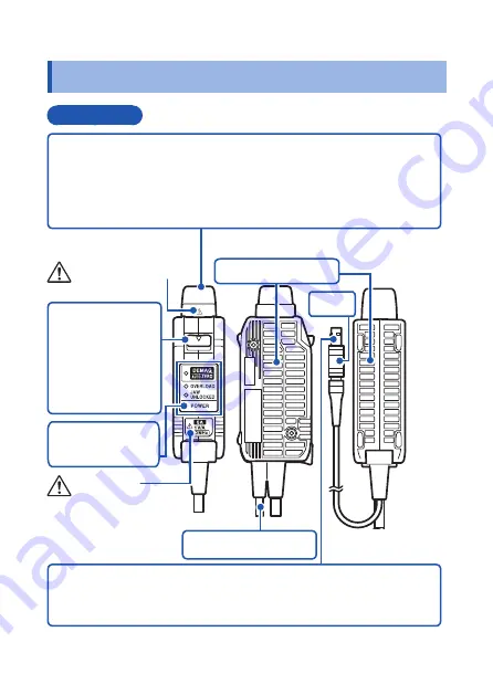
1.3  Parts Names and Functions

Terminator

Upper 

side

Bottom side

Output connector

The current waveform of the measured conductor is output at a 

constant rate (1 V/A).

Connect to the BNC input connector of the waveform 

measurement instrument.

Unlock lever

The output 

connector can be 

disconnected by 

pulling this part 

toward you.

Power supply cord

Ventilation holes

Side

Power plug

Connect this to the 3269 or the 3272 Power Supply to supply 

power to the sensor terminator.

Shell

See p. 10.

See p. 7 and p. 14.

Key and LEDs
(p. 28)

Summary of Contents for CT6700

Page 1: ...EN EN CT6701 CURRENT PROBE CT6700 Instruction Manual Nov 2017 Revised edition 3 CT6700A981 03 17 11H CT6701 CURRENT PROBE CT6700 Instruction Manual Nov 2017 Revised edition 3 CT6700A981 03 17 11H...

Page 2: ......

Page 3: ...asurement Procedure 33 2 1 Inspection Before Use 33 2 2 Preparation for Measurements 35 Connecting the device to the Power Supply 35 Performing Demagnetizing and Zero Adjustment 37 2 3 Performing Meas...

Page 4: ...ii Contents...

Page 5: ...t fails to operate according to the specifications contact your dealer or Hioki representative Check the package contents as follows CT6700 CT6701 Current Probe Carrying Case Instruction Manual The pr...

Page 6: ...read the following safety notes DANGER Mishandling during use could result in injury or death as well as damage to the device Be certain that you understand the instructions and precautions in the ma...

Page 7: ...moderate injury to the operator or damage to the device or malfunction IMPORTANT Indicates information related to the operation of the device or maintenance tasks with which the operators must be full...

Page 8: ...This symbol indicates that the electrical and electronic appliance is put on the EU market after August 13 2005 and producers of the Member States are required to display it on the appliance under Ar...

Page 9: ...he cord is undamaged and that no bare conductors are improperly exposed Using the device in such conditions could cause an electric shock so contact your dealer or Hioki representative for repair Befo...

Page 10: ...posed to a strong electromagnetic field or electrostatic charge Exposed to high quantities of dust particles Near induction heating systems such as high frequency induction heating systems and IH cook...

Page 11: ...er Supply Check that the conductor being measured is not clamped when supplying power to the device A demagnetizing waveform may be generated when power is supplied causing damage to components connec...

Page 12: ...ument oscilloscope recorder etc that has an input impedance of at least 1 M Accurate measurement is not possible with waveform measurement instruments that have an input resistance of 50 An AC voltage...

Page 13: ...e due to self heating and other factors Offset drift will occur when the ambient temperature changes or when the device is used to make continuous measurements over an extended period of time causing...

Page 14: ...asure any current that exceeds the rated current Use with high frequencies or strong magnetic fields may cause the device to become abnormally hot resulting in fire equipment damage or burns See 3 Spe...

Page 15: ...ay attention to the following points The device s reference potential is the ground potential Do not apply a different potential to the ground side of other input connectors Otherwise short circuit cu...

Page 16: ...rm measurement instrument and other measurement instruments to which this device is connected This device should only be connected to the secondary side of a breaker so the breaker can prevent an acci...

Page 17: ...conductor being measured is clamped Doing so could damage the circuitry or cause an accident that might result in injury or death Conductor Demagnetizing Ensure that the input does not exceed the max...

Page 18: ...faces of the sensor head insert foreign objects into the gaps of the sensor head or touch the mating faces Doing so may worsen the performances of the sensor or interfere with clamping action Do not a...

Page 19: ...the sensor head and cause its temperature to rise leading to damage to the device For example when one side of a go and return conductor is clamped and the other side is also placed near the sensor h...

Page 20: ...p 50 The product specifications that indicate the maximum input range include a maximum peak current value of 7 5 A peak non continuous in addition to the maximum rated current This value constitutes...

Page 21: ...s which could interfere with clamp performance The sensor head is a precision assembly including a molded component a ferrite core and a Hall effect element To prevent damage avoid abrupt temperature...

Page 22: ...tric shock Remove the device from the conductor being measured immediately The device must be allowed to cool adequately before resuming normal use The maximum rated current varies according to the fr...

Page 23: ...Confirm that the total current consumption of the device does not exceed the rated output current of the 3272 When using the 3272 confirm that the total current consumption of the device does not exce...

Page 24: ...aperture of the conductor being measured The conductor should be in the center of the sensor aperture and the straight portion should be as long as possible Avoid positioning the conductor so that it...

Page 25: ...g on the amplitude and frequency of the current being measured the sensor head may emit a resonant sound This sound may also occur during demagnetizing operation but it does not represent a malfunctio...

Page 26: ...connector from the waveform measurement instrument Always grip the terminator and pull the unlock lever toward you before disconnecting the connector Observe the following precautions when disconnect...

Page 27: ...Overview This device can be directly connected to a BNC input connector of a waveform measurement instrument such as an oscilloscope or recorder and by clamping on a conductor being measured allows t...

Page 28: ...n the locking pin on the waveform measurement instrument s BNC input connector is in either the horizontal or vertical orientation 4 LED warnings are displayed when an overload occurs and when the sen...

Page 29: ...constant rate 1 V A Connect to the BNC input connector of the waveform measurement instrument Unlock lever The output connector can be disconnected by pulling this part toward you Power supply cord Ve...

Page 30: ...Sensor head This clamps the conductor being measured and carries out the actual current measurement Sensor cord Upper side Side Opening lever Operating lever for opening the sensor head Always use th...

Page 31: ...27 Parts Names and Functions CAUTION To prevent sensor head damage avoid abrupt temperature changes stress mechanical shock application of static electricity and other problematic phenomena...

Page 32: ...ero adjustment Off After demagnetization and zero adjustment POWER LED Lit up continuously green When energized JAW UNLOCKED LED Lit up continuously red When the sensor head is unlocked OVERLOAD LED S...

Page 33: ...AG AUTO ZERO 1 s 1 1 1 1 1 3 times OVERLOAD 1 s 3 times JAW UNLOCKED 1 s 3 times POWER 1 When the JAW UNLOCKED LED is lit up or the OVERLOAD LED is ashing the DEMAG AUTO ZERO LED will not be lit even...

Page 34: ...35 1 Verify that the 3269 or 3272 is turned off and connect the power cord to the AC electrical outlet 2 Lock the device s sensor head 3 Connect the power plug of the device to the 3269 or the 3272 4...

Page 35: ...ents p 41 1 Clamp the device around the conductor being measured 2 Lock the device s sensor head 3 Observe the current waveform with a waveform measurement instrument Finishing Measurements p 43 1 Rem...

Page 36: ...3269 or Model 3272 Power Supply Power Source Load Load Reference The above figure illustrates an example connection between the device and a normal oscilloscope or other instrument that does not have...

Page 37: ...ore Use Before using the device for the first time verify that it operates normally to ensure that no damage occurred during storage or shipping If you find any damage contact your authorized Hioki di...

Page 38: ...r This may cause an electric shock No 2 Is the insulation on the cord damaged Yes No 3 Do all the LEDs light up for 1 second after the device is powered on p 35 No The device is broken and should be r...

Page 39: ...rrent Probe Model 3269 or Model 3272 Power Supply option Waveform measurement instrument oscilloscope recorder or etc Connecting the device to the Power Supply Procedures 1 Verify that the POWER switc...

Page 40: ...tacle of the 3269 or the 3272 Power receptacle 3 Turn the 3269 or 3272 POWER switch on Verify the following Model 3269 or 3272 Power Supply The front panel POWER indicator light Model CT6700 or CT6701...

Page 41: ...tizing and Zero Adjustment Always carry out demagnetizing and zero adjustment before measurement The demagnetizing and zero adjustment process takes about 20 seconds What is Demagnetizing Demagnetizat...

Page 42: ...l be output from the device s output connector and displayed on the waveform measurement instrument The positive and negative components of this waveform may be asymmetrical but this does not represen...

Page 43: ...m measurement instrument to DC 3 Connect the output connector of the device to the BNC input connector of the waveform measurement instrument Insert the connector until it clicks into place so that it...

Page 44: ...demagnetization and zero adjustment The LED stops flashing and lights up continuously After demagnetization and zero adjustment complete normally The LED turns off If the DEMAG AUTO ZERO LED continue...

Page 45: ...escribed steps Procedures 1 Pull the sensor opening lever so that the sensor head opens Opening lever 2 Clamp the conductor being measured Clamp so that the conductor is in the center of the sensor ap...

Page 46: ...d To perform high precision measurement perform the steps listed below before clamping around the conductor being measured Additionally manipulate the lever gradually when closing the sensor and avoid...

Page 47: ...asured Opening lever 2 Disconnect the terminator from the waveform measurement instrument Pull the connector straight out while pulling the unlock lever toward you Terminator can be held using just tw...

Page 48: ...r plug of the device from the 3269 or the 3272 Grip the power supply plug s shell p 25 when disconnecting it Do not pull on cords to disconnect them or twist the power supply plug 5 Unplug the 3269 or...

Page 49: ...ty range 0 C to 40 C 32 F to 104 F 80 RH or less no condensation Storage temperature and humidity range 10 C to 50 C 14 F to 122 F 80 RH or less no condensation Location for use Indoor pollution degre...

Page 50: ...o be less than 5 A rms Maximum peak current 7 5 A peak non continuous Output voltage rate 1 V A Amplitude accuracy 3 0 rdg 1 mV typical 1 0 rdg 1 mV DC and sine wave 45 to 66 Hz 0 to 5 A rms Example r...

Page 51: ...nput Supply voltage 12 V 0 5 V Effect of external magnetic fields 20 mA or less DC and 60 Hz Magnetic field of 400 A m 5 mA or less DC and 60 Hz Magnetic field of 400 A m Effect of radiated radio freq...

Page 52: ...er supply cord 1 m 0 1 m 39 37 3 94 External dimensions Sensor Approx 155W 18H 26D mm approx 6 10 W 0 71 H 1 02 D excluding protrusions Terminator Approx 29W 83H 40D mm approx 1 14 W 3 27 H 1 57 D exc...

Page 53: ...1M 10M 100M 1000M Gain dB Frequency Hz 1G 40 30 20 10 0 10 1 10 Gain dB Fig 1 Frequency characteristics typical CT6700 1G Gain dB Frequency Hz 100M 1000M Frequency Hz 1G 40 30 20 10 0 10 1 10 100 1k 1...

Page 54: ...current A Frequency Hz 1G 1G TA 23 Sine wave 0 1 2 3 4 5 6 100 Maximum input current A TA Fig 3 Derating according to frequency CT6700 1G 00M 1000M Frequency Hz 1G 1G 0 1 2 3 4 5 6 100 1k 10k 100k 1M...

Page 55: ...and with sine wave input If the ambient temperature TA rises or the current being measured contains a high frequency component the device s temperature will rise and the current value and frequency t...

Page 56: ...o account when performing high frequency measurement 0 001 0 01 0 1 1 100 1 Input impedance 0 001 0 01 0 1 1 100 1k 10k 100k 1M 10M 100M 1000M Input impedance Frequency Hz 1G 1G Fig 6 Input impedance...

Page 57: ...ffect on conductor being measured inside sensor aperture common mode voltage 180 160 140 120 100 80 60 100 1k 10k 100k 1M 10M Output volt Common mode volt dB Frequency Hz Fig 8 Effect of common mode v...

Page 58: ...ical 2 Zero adjustment Operation Performs zero adjustment User action Press and hold the DEMAG AUTO ZERO key for at least 20 ms but less than 500 ms typical Cannot be performed in the following circum...

Page 59: ...er demagnetization terminated abnormally Continuous orange During demagnetization and zero adjustment Off After demagnetization and zero adjustment Sensor head unlocked detection The JAW UNLOCKED LED...

Page 60: ...ms DC 45 to 66 Hz sine wave 2 Rating exceeded Indicates that the maximum rated current has been exceeded OVERLOAD LED Red fast flashing Flashing conditions If prescribed level 2 is exceeded Prescribed...

Page 61: ...calibration is necessary in order to ensure that the device provides correct measurement results of the specified accuracy The calibration frequency varies depending on the status of the device or in...

Page 62: ...even after performing demagnetization and zero adjustment p 37 internal damage may have occurred Contact your authorized Hioki distributor or reseller If you must send the device out for repair pack...

Page 63: ...may be emitted depending on the amplitude and frequency of the current being measured Such a sound may also be emitted during demagnetization Measurement is not affected The resonant sound emitted by...

Page 64: ...ting the suggested remedy Circumstances Remedy When the JAW UNLOCKED LED is lit up Lock the sensor head Press the opening lever until the JAW UNLOCKED indicator turns off When the OVERLOAD LED is flas...

Page 65: ...been detected due to heating caused by an overload Remove the device from the conductor being measured immediately Allow the device to cool under conditions of no input and then press the DEMAG AUTO...

Page 66: ...gnetization and zero adjustment p 37 again after implementing the remedy described below Circumstances Remedy When the JAW UNLOCKED LED is lit up Lock the sensor head Press the opening lever until the...

Page 67: ...es clean by gently wiping with a soft cloth Before cleaning the facing surfaces on the sensor head discharge any static electricity that may have built up on your hands by touching a nearby metal obje...

Page 68: ...64 Discarding the Device 4 4 Discarding the Device Handle and dispose of the device in accordance with local regulations...

Page 69: ...16 01 EN...

Page 70: ......

Page 71: ......

Page 72: ......

Reviews: