background image

1.3  Parts Names and Functions

14

Frequency

24

Duty factor

31

V

REC

MEMO

RANGE

( 1 - 4 )

"Hz" 

lights up

Measure-

ment

V

REC

MEMO 

2

RANGE

( 1 - 4 )

(              )

Measure-

ment

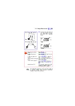
Hold the measured value.

(HOLD AUTO function)

This function is used when the displayed value cannot be checked during 
measurement (such as when necessary to measure the conductor in a 
dark place or using both hands.

33

Hold the measured value.

(HOLD function)

34

"O.F" is displayed to provide a warning

(Overflow Warning function)

When the measured value exceeds the maxi-
mum value, "O.F" is displayed.

35

Use this function to check any discrepancy from the reference,
or to control the resistance for the purpose of zero adjustment

(Relative function)

Cancellation: 

H.AUTO/REL

 (press again)

36

Quick Reference (application)

: Turn on the power while pressing 

the button (hold the button down 
until a beeping sound is generated).

:Button

REC•MEMO

REC•MEMO

<1 second: 
Press the button for at least 1 second.

Example

V/

V/

/

40

A/

A/mA/

10A

H.AUTO/REL

"HOLD"
Blinking

(Intermittent 

sound)

Move the test leads away from 

the measurement object.

V/

V/Hz/

/

/

/

/

40

A/

A/mA/

10A

H.AUTO/REL

H.AUTO/REL

Measure-

ment

V/

V/40

A/

A/mA/10A

V/

V/

/

40

A/

A/mA/

10A

H.AUTO/REL

Display the 
reference.

(<1 second)

("REL"

 lights up)

Summary of Contents for 3257-50

Page 1: ...3257 51 DIGITAL HiTESTER 3257 50 Instruction Manual June 2012 Revised edition 9 3257C981 09 12 06H...

Page 2: ......

Page 3: ...oltage Measurement 22 2 3 Frequency Measurement 24 2 4 Current Measurement 25 2 5 Resistance Measurement 28 2 6 Continuity Check 29 2 7 Diode Check 30 2 8 Duty Factor Measurement 31 Chapter 3 Addition...

Page 4: ...ions 43 4 1 General Specifications 43 4 2 Accuracy 46 4 3 L9207 10 TEST LEAD Specifications 49 Chapter 5 Maintenace and Service 50 5 1 Replacing the Batteries and Fuses 50 5 2 Cleaning 52 5 3 Service...

Page 5: ...ions contact your dealer or Hioki representative Before using the product the first time verify that it operates normally to ensure that the no damage occurred during storage or shipping If you find a...

Page 6: ...g the product be sure to carefully read the fol lowing safety notes 3257 50 1 3257 51 2 Accessories Safety Notes This product is designed to conform to IEC 61010 Safety Standards and has been thor oug...

Page 7: ...cates that the user should refer to a corresponding topic in the manual marked with the symbol before using the relevant function Indicates that dangerous voltage may be present at this terminal Indic...

Page 8: ...e user Indicates that incorrect operation presents a pos sibility of injury to the user or damage to the prod uct Advisory items related to performance or correct operation of the product Indicates th...

Page 9: ...of a measurement instrument that is not CAT rated in CAT II to CAT IV measurement applications could result in a severe accident and must be carefully avoided CAT II Primary electrical circuits in eq...

Page 10: ...nefits of the various func tions Usage Notes To avoid electric shock do not allow the product to get wet and do not use it when your hands are wet Do not use the product where it may be exposed to cor...

Page 11: ...usty environment Do not use the product near a device that gener ates a strong electromagnetic field or electro static charge as these may cause erroneous measurements To avoid damage to the product p...

Page 12: ...and mean There are two methods for converting AC signal to an RMS value the true RMS method true RMS indication and the mean method mean rectification RMS indication Although the two methods both yiel...

Page 13: ...ents in the and CAT II measurement categories For details on measurement categories see Measurement categories page 5 in the instruction manual To prevent an electric shock accident con firm that the...

Page 14: ...digital multimeter The measurement product is equipped with test lead misinsertion preventive shutters and fast act ing fuses at the current measurement terminals Multi functional and duty factor meas...

Page 15: ...sed to measure currents in A mA mode V terminal Terminal used to measure voltag es and resis tances red test lead COM terminal Terminal common to all functions black test lead REC MEMO Button Press th...

Page 16: ...35 0 15 V Decimal point Changes to the function indicated in blue Toggles between AC and DC modes Current measurement page 25 Recording function Displays MAX MIN AVG 1 page 39 Duty Factor mea surement...

Page 17: ...AC current function mA DC AC current function 10A DC AC current function Function Selector Press REC MEMO when the function in parentheses is being used Quick Reference Indicates the function selecto...

Page 18: ...the maxi mum value O F is displayed 35 Use this function to check any discrepancy from the reference or to control the resistance for the purpose of zero adjustment Relative function Cancellation H A...

Page 19: ...Save the measured value to memory Memory function 40 Call the saved data 41 Delete all data from memory 41 V V Hz 40 A A mA 10A REC MEMO Press this button until a beeping sound is generated OFF Functi...

Page 20: ...sleeve removed Diameter approx 2 mm Sleeve Attach to the pins to prevent short circuit accidents Barrier Represents the safe handling distance from the pins Cable Double sheathed cables Length Approx...

Page 21: ...the and CAT II measurement categories For details on measurement categories see Measurement categories page 5 in the instruction manual To prevent an electric shock accident con firm that the white o...

Page 22: ...he sleeves and pull the sleeves off Safely store the re moved sleeves so as not to lose them Remove the protective cap installed at the time of shipment before using the instrument The red plastic ins...

Page 23: ...m the mea surement object before switching the func tion selector When it is necessary to replace the mea surement terminal remove the test lead from the measurement object and discon nect the lead fr...

Page 24: ...use the instrument Required equipment Model 3257 50 51 this instrument Model L9207 10 TEST LEAD AC power receptacle 100 V AC 50 60Hz commercial power supply 1 Set the function switch to the continuity...

Page 25: ...sounds Value stabilizes around 0 OK OF displayed The display is unstable NO Possible test leads or tester malfunction Black Red Display of commercial voltage levels OK No display of commercial voltag...

Page 26: ...always be made at the secondary side of a circuit breaker The maximum rated voltage between input terminals and ground is 1000 VDC AC CAT III 600 VDC AC CATIV or 107 V Hz Attempting to measure voltag...

Page 27: ...Move the test leads away from the measurement object Press H AUTO REL Power on Measurement Press H AUTO REL Appearance of O F The measured value exceeds 4200 counts up to the 420 V range or 1050 coun...

Page 28: ...z lights up 2 Connect the red test lead to terminal V and the black test lead to terminal COM 3 Select the input level 1 to 4 using the RANGE button in accordance with the input volt age 4 Connect the...

Page 29: ...ach range 40 A A mA range 420mADC 420 mA rms 10A range 10 ADC 10 A rms Do not input a current in excess of this value Otherwise the measurement prod uct will be damaged resulting in an acci dent that...

Page 30: ...terminal COM 4 Connect the test leads to the measurement object and read the indicated value The Auto Range function is not provided A Measurement 420 A 4200 A range Red Black REC MEMO 1 Move the func...

Page 31: ...ement 10 A range Note that the product may be damaged if current exceeding the selected measurement range is applied for a long time for the 10 A range continu ous current must be limited to 7A or to...

Page 32: ...the position 2 Connect the red test lead to termi nal V and the black test lead to terminal COM 3 Connect the test leads to the measurement object and read the indicated value Selecting the manual ran...

Page 33: ...from the circuit before measuring Black Red REC MEMO Black Red 1 Move the function selector to the position 2 Select Diode using the REC MEMO button lights up 3 Connect the red test lead to termi nal...

Page 34: ...ed REC MEMO Cathode Anode Black Red 1 Move the function selector to the position 2 Select Diode using the REC MEMO button lights up 3 Connect the red test lead to ter minal V and the black test lead t...

Page 35: ...ide slope D D tw T 100 2 8 Duty Factor Measurement The maximum input voltage is 1000 VDC 1000 Vrms or 107 V Hz Attempting to measure voltage in excess of the maximum input could destroy the product an...

Page 36: ...indicating that a positive slope is being mea sured To measure a negative slope press the REC MEMO button again lights up 2 Connect the red test lead to ter minal V and the black test lead to terminal...

Page 37: ...than 400 counts other range A A less than 40 counts O F 1 Select the desired function and connect the test leads to the measurement product 2 Press the H AUTO REL button HOLD blinks In the measurement...

Page 38: ...n until a beeping sound is generated toggle the function selector to the desired position 2 Press the H AUTO REL button again at the measured value to be held The value is held HOLD lights up 3 To can...

Page 39: ...ge of DC voltage measurement V or AC voltage measurement V 10 A range of current measurement Example When the measured value exceeds 1050 counts in the 1000 V range of AC voltage measurement V 3 3 Ove...

Page 40: ...e button at 10 V REL lights up and 0000 is displayed 4 Measure the voltage again and read the displayed value discrepancy from the reference The measured value minus the reference is displayed Checkin...

Page 41: ...The resistance of the test leads is displayed 3 Press the H AUTO REL button for at least 1 sec ond REL lights up 0000 4 Connect the test leads to the measurement object and read the indicated value Ap...

Page 42: ...ave Function Functions All functions Description Approximately 10 minutes after completing final operation the measurement product automati cally enters Power Save mode When the mea surement product i...

Page 43: ...product 2 Connect the test leads to the measurement object 3 Press the REC MEMO but ton for at least 1 second MAX MIN AVG lights up 4 Select the item using the H AUTO REL button Current value Maximum...

Page 44: ...using the Hold Auto or Hold function 2 Press the REC MEMO button in hold mode The value dis played is saved in memory of the number specified Wait a moment for current value display on the LCD Up to...

Page 45: ...NGE button to select the memory number The saved data is displayed on the LCD Deleting all data from memory In Memory Call mode press the REC MEMO and RANGE buttons simultaneously for at least 1 secon...

Page 46: ...3 7 Memory Function 42...

Page 47: ...n Hold function Hold Auto function Relative Display Function Dynamic Recording function Memory function Registration call deletion Auto Power Save function Overflow Warning function Battery Life Warni...

Page 48: ...ous Operating Time Approx 100 hours V with R03 manganese batteries Approx 200 hours V with LR03 alkaline batteries Maximum Rated Voltage to Earth 1000 VDC 1000 Vrms sin or 107V Hz CAT III 600 VDC 600...

Page 49: ...W 6 57 H 1 30 D without protrusions Approx 260 g 9 2 oz Accessories L9207 10 TEST LEAD Instruction Manual Two R03 manganese batteries Protective holster 3257 51 or 9378 CARRYING CASE 3257 50 Applicab...

Page 50: ...gt resolution Voltage Measurement Range V Accuracy rdg dgt Input Impedance Frequency range V 420 0 m 4 200 42 00 420 0 1000 0 5 2 0 5 2 0 5 2 0 5 2 0 5 2 100 M or more Approx 11M Approx 10M Approx 10M...

Page 51: ...d Maximum input voltage 1000 Vrms sin or 107 V Hz Resistance Measurement Continuity Check Diode Check Range Accuracy rdg dgt Openterminal voltage Measurement current max Reference value Resis tance 42...

Page 52: ...reaking capacity10 kA 10A range 11 A 1000 V AC DC Breaking capacity 17 kA 1000 VAC 10 kA 1000VDC 1 The above measurement accuracies are applied to input of at least 10 of the full scale Crest factor 3...

Page 53: ...eves attached Sleeves removed Maximum rated voltage to earth 1000 V Measurement category III Anticipated transient overvoltage 8000 V Maximum rated voltage to earth 600 V Measurement category IV Antic...

Page 54: ...ld and new batteries or dif ferent types of batteries Also be careful to observe battery polarity during instal lation Otherwise poor performance or damage from battery leakage could result To avoid t...

Page 55: ...ittelfuse Inc Cooper Industries Inc Bussmann Division USA 1 Disconnect the test leads from the measurement circuit and make sure the function selec tor is in the OFF position 2 Position the measuremen...

Page 56: ...ries are not discharged and that the test leads and fuse are not open cir cuited before contacting your dealer or Hioki rep resentative To avoid corrosion from battery leakage remove the batteries fro...

Page 57: ......

Page 58: ......

Reviews: