Himmelstein MCRT 48200V Troubleshooting Manual Download Page 6

6

© 2022 S. Himmelstein and Company—all rights reserved.     www.himmelstein.com

B. Electrical Installation

B.1 Applicability

This section applies to all MCRT

®

  48200V Torquemeters.

B.2 Stator Connectors

Three stator connectors are used, as follows:

•  Input Power (2 Pins)

•  Analog Output/Cal Enable/Zero (4 Pins)

•  Com Port (3 Pins)

If an optional speed pickup is furnished, it will have an 
integral 2 pin (Code A) or 3 pin (Code Z) connector. 

The 

Code Z Zero Velocity Pickup is recommended for use 
at low operating speed and for electrically noisy envi-
ronments.

 Mating connectors are supplied except if a 

complete cable is furnished for the Com Port.

Before wiring mating connectors, refer to Figure 5 for the 
connector pin number identification(s). That Figure shows 
the stator connector looking down at the torquemeter. 
Mating connector pin sequence is their mirror image.

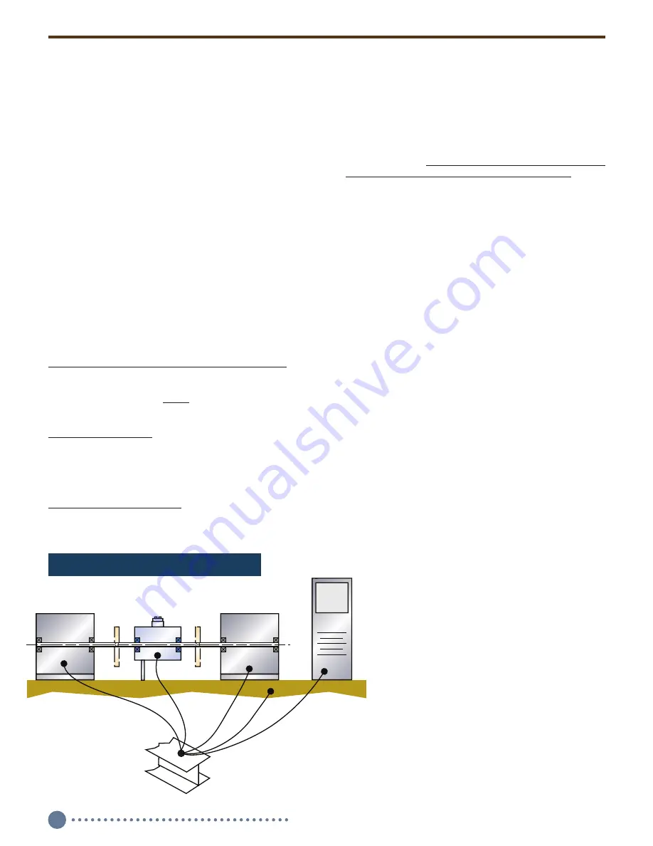
B.2.1 Earth Ground Connection

Connect  the Torquemeter  stator directly to earth ground, a 
buildings’ structural steel or a floor rod. If neither is avail-
able, drive a six foot copper rod into the floor. Then run 
separate ground straps between it, the drive motor frame, 
the machine base, the torquemeter housing, the load 
device and the data acquisition/computer system ground. 
Don’t “daisy chain” the connections. See Figures 3 and 4.

If an IGBT-based variable frequency drive (VFD) is used, 
follow its installation manual. Improperly installed VFD’s 
can cause premature motor and cable failures, and 
reading errors from excessive noise. VFD’s should have 

shielded power and motor cables. Belden Types 29500 
thru 29507 cable are designed for VFD use. See “Cable 
Alternatives for PWM AC Drive Applications” available at 
www.belden.com. Himmelstein recommends the connec-
tion in 

Figure 20

. For best results, use a differential input 

amplifier in these electrically noisy environments.

B.2.2 Power Input; 2 Pin Connector

The power connector has two pins with pinout as follows:


Pin 1 

Power Return


Pin 2 

+ Power In ( 10 to 15 VDC)

Spare mating connectors can be ordered from the factory; 
P/N: 320-1285.

Reverse polarity protection is standard. Although any wire 
may be used for connections, 

shielded cable will perform 

best in noisy environments and is recommended

. Note: 

the shield should float at the Torquemeter end. The other 
end should be tied to earth ground; see Figure 5.

Caution: Don’t connect a Torquemeter to a 
Power Supply that also drives inductors or 
solenoids. Induced switching transients may 
cause damage or noise.

B.2.3 Analog Outputs, Cal Enable, Torque 
Zeroing; 4 Pin Connector

Shielded cable is recommended for these connections. 
The shield should float at the Torquemeter end and tied 
to earth ground at the other end; See Figure 5. Spare 
mating connectors can be ordered from the factory; P/N: 
320-1287.

B.2.3.1 Analog Outputs
An analog of Torque is output on the four pin connector.
Pin connections are as follows:

  Pin 1 

Analog Output

  Pin 2 

Analog Ground

The analog signal may have full scale values as 
follows:

  Torque  CW = +10V, CCW = -10V, or
 

CW = +5V, CCW = -5V

The default value is 10 Volts. The user may reas-
sign the output voltage selection with the use of 
a PC and supplied software. CW torque causes 
the shaft to turn CW when viewed from the 
driven end. CCW torque causes the opposite 
rotation.

B.2.3.2 Cal Check Enable
Internal Calibration Check Circuitry may be 
remotely enabled by pin strapping and/or via 

Load Device

DAS/Controller

Machine Base

Drive Motor

Torquemeter

Earth Ground

NOTE: Use separate

ground straps.

Figure 3. Correct System Earth Grounding.

Summary of Contents for MCRT 48200V

Page 1: ...NON CONTACT DIGITALTORQUEMETER INSTALLATION OPERATION ANDTROUBLESHOOTING GUIDE MCRT 48200V NON CONTACT DIGITALTORQUEMETER INSTALLATION OPERATION ANDTROUBLESHOOTING GUIDE COMPANY 2490 Pembroke Avenue H...

Page 2: ...te Unless specified differently when ordered default values are as follows Sensor Full Scale 10 Volts Torque Unit of Measure lbf in Filter Cutoff Frequency 10 Hz Password Protection Off These selectio...

Page 3: ...D 2 3 Starting High Inertias with Electric Motors 10 D 3 Allowable Bearing Loads 11 D 4 Allowable Extraneous Loads 11 D 4 1 Allowable Bending Loads 11 D 4 2 AllowableThrust Loads 11 D 5 Operating Spee...

Page 4: ...tude variations That data is then transmitted to the stator as infrared IR energy where it is detected and output in industry standard analog and digital formats The IR transmission is inherently tole...

Page 5: ...force Next allow the assembly to cool to room temperature Then repeat the process for the second coupling If desired use forced air to accelerate cooling Air cooling avoids contaminating the torque m...

Page 6: ...ailable at www belden com Himmelstein recommends the connec tion in Figure 20 For best results use a differential input amplifier in these electrically noisy environments B 2 2 Power Input 2 Pin Conne...

Page 7: ...1 Zero Velocity Code Z Pickup Code Z Zero Velocity Speed Pickups have three pin connectors They require external power 6 to 15VDC Connections are as follows Pin A Power In 6 to 15VDC Pin B Output Sig...

Page 8: ...pe A Pin A Signal Pin B Signal Type Z Pin A POWER IN Pin B Output Signal Pin C Common Notes 1 A dot appears next to Pin 1 on all connectors 2 All cables are shielded 3 Shields Float at Torquemeter end...

Page 9: ...c data with unit of measure Displays Torque Peak and Valley numeric data with unit of measure Displays Torque Spread numeric data with unit of measure Classifies status of user set High and Low Torque...

Page 10: ...taneous torque and the torquemeters overload rating as a safety margin for unexpected loads Do not knowingly operate in the overload region If you expect torques in the overload region then change to...

Page 11: ...inches of bending or 1 of the applied pounds of thrust D 4 1 Allowable Bending Loads When it is applied without thrust a standard MCRT Torquemeter mounted as a floating shaft can handle a shaft bendi...

Page 12: ...ntial faults The best procedure is to isolate the problem part then correct or replace it Otherwise return the defective part to the factory E 2 Preliminary Inspection E 2 1 Torquemeter Inspect the se...

Page 13: ...1 Hertz If the readings become steady then you may wish to identify the physical cause of the shaft torque variation or remove it with mechanical filtering techniques Oscillographic signal analysis i...

Page 14: ...nominal Has reverse polarity and 25 Volt overvoltage protection Available Options Enhanced Performance Code C Code N is standard performance 60 PPR Speed Pickup Options Code A is standard type Code Z...

Page 15: ...or aType A pickup and 3 pins for aType Z pickup To order spare connectors use the following part numbers P N When the bearing load ratings don t meet the above criteria use pillow blocks and a jack sh...

Page 16: ...it mantissa with an implied MSB of 1 0x80000000 Sign 0 positive 1 negative 0x7F800000 Exponent 0x007FFFFF Mantissa o if sign 0 then value 2 Exponent 24 Mantissa 0x800000 o else value 2 Exponent 24 Man...

Page 17: ...se messages can only retrieve information from the MCRT48200V they can not change any data on the MCRT48200V The time returned is the number of 10kHz clock ticks since the MCRT48200V was powered on ME...

Page 18: ...ut E DAC value to give 10V analog output Miscellaneous Messages MESSAGE REPLY MEANING OK Write data in RAM to non volatile flash PS index string OK Change Flash password protection o string must match...

Page 19: ...the user Only data from the DC command is subject to this scaling FL int FiLter 0 10 4 bits o 2 200 Hz o 3 100 Hz o 4 50 Hz o 5 20 Hz o 6 10 Hz o 7 5 Hz o 8 2 Hz o 9 1 Hz o 10 0 5 Hz o 11 0 2 Hz o 12...

Page 20: ...COMPANY 2490 Pembroke Avenue Hoffman Estates IL 60169 847 843 3300 www himmelstein com CDTM...

Reviews: