HiLook THC-B320-VF User Manual Download Page 7

Note: 


The supplied screw package contains self-tapping 

screws, and expansion bolts. 


For cement wall, expansion bolts are required to fix 
the camera. For wooden wall, self-tapping screws are 

required. 

5.


Connect the corresponding power cord, and video 

cable. 

6.


Power on the camera to check whether the image 

on the monitor is gotten from the optimum angle. If 

not, adjust the surveillance angle. 

0° to 360°

3

2

1

0° to 360°

0° to 90°


Figure 2-3


3-axis Adjustment 

1)


Loosen the No.

  adjusting screw to adjust the 

pan position [0° to 360°]. Tighten the No.


adjusting screw. 

2)


Loosen the No.

  adjusting screw to adjust the 

tilting position [0° to 90°]. Tighten the No.


adjusting screw. 

3)


Loosen the No.

  adjusting screw to adjust the 

rotation position [0° to 360°]. Tighten the No.


adjusting screw. 

2.2


Installation of Type II Camera 

Before you start: 
Both wall mounting and ceiling mounting are suitable 

for the bullet camera. Ceiling mounting will be taken as 
an example in this section. And you can take steps of 
ceiling mounting as a reference for wall mounting. 
Steps: 
1.


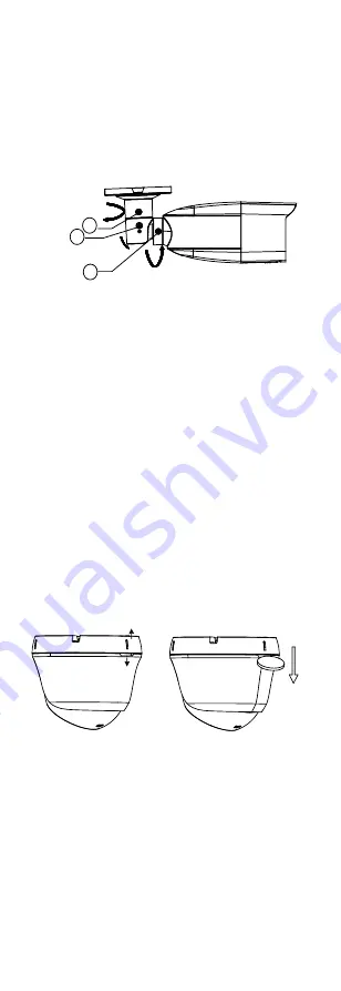
Disassemble the turret camera by rotating the 
camera to align the notch to one of the marks, as 

shown in the figure below. 

Mark

Notch


Figure 2-4


Disassemble the Camera 

2.


Remove the mounting base from the camera body 

with a flat object, e.g., a coin 

3.


Paste the drill template to the place where you want 
to install the camera. 

4.


Drill the screw holes according to the drill template 

and the cable hole (optional) in the ceiling. 

Summary of Contents for THC-B320-VF

Page 1: ...elow Type Model Type I Camera THC B320 VF THC B340 VF Type II Camera THC T320 VF THC T340 VF Type III Camera THC D320 VF THC D340 VF This manual may contain technical incorrect places or printing erro...

Page 2: ...se undesired operation EU Conformity Statement This product and if applicable the supplied accessories too are marked with CE and comply therefore with the applicable harmonized European standards lis...

Page 3: ...mounting is adopted If smoke odor or noise rise from the device turn off the power at once and unplug the power cord and then contact the service center Never attempt to disassemble the camera by unpr...

Page 4: ...rom liquid while in use for non water proof device While in delivery the camera shall be packed in its original packing or packing of the same texture Mark Description Table 0 1 Mark Description Mark...

Page 5: ...erview of Type I Camera Lens Main Body Bracket Switch Button Power Cord 12 VDC Video Cable Figure 1 1 Overview of Type I Camera 1 2 2 Overview of Type II Camera DC12V IN Enclosure Main Body Mounting B...

Page 6: ...tion properly contact your dealer or the nearest service center Do NOT disassemble the camera for repair or maintenance by yourself 2 1 Installation of Type I Camera Before you start Both wall mountin...

Page 7: ...the No adjusting screw 3 Loosen the No adjusting screw to adjust the rotation position 0 to 360 Tighten the No adjusting screw 2 2 Installation of Type II Camera Before you start Both wall mounting a...

Page 8: ...iling expansion bolts are required to fix the camera For wooden ceiling self tapping screws are required 6 Route the cables through the cable hole or the side opening 7 Align the camera with the mount...

Page 9: ...example in this section You can take steps of ceiling mounting as a reference for wall mounting Steps 1 Paste the drill template to the celling 2 Drill screw holes and the cable hole optional on the c...

Page 10: ...wer cable and video cable 7 Power on the camera to check whether the image on the monitor is gotten from the optimum angle If not adjust the camera according to the figure below to get an optimum angl...

Page 11: ...the PTZ Control interface 4 Call the camera menu by clicking button or click Iris GLOBAL MAIN MENU DAY NIGHT VIDEO SETTINGS EXIT SAVE EXIT BLC DWDR COLOR B W CONTRAST SHARPNESS AGC DNR MIRROR EXPOSUR...

Page 12: ...eas simultaneously exist in the image DWDR balances the brightness level of the whole image to provide clear images with details 3 3 DAY NIGHT COLOR BW Black White and AUTO are selectable for DAY NIGH...

Page 13: ...ontrol the sensitivity of switching the day mode to the night mode You can set the value from 1 to 9 The larger the value is the more sensitive the camera is N D Threshold Night to Day Threshold Night...

Page 14: ...set the DNR as HIGH MEDIUM or LOW AGC It optimizes the clarity of the image in poor light conditions The AGC level can be set as High Medium or Low Select OFF to disable the AGC function Note The noi...

Reviews: