background image

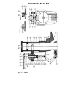
Exploded View: 25t Toe Jack


Plan No. 28790-06 

16 

Summary of Contents for HTJ-10

Page 1: ...Toe Jack Instruction Manual Models HTJ 5 HTJ 10 and HTJ 25 12 Timber Lane Marlboro NJ 07746 tel 732 462 6277 fax 732 462 6355 email sales hilmanrollers com ...

Page 2: ...FIELD OF USE 5 2 OPERATION 5 3 SAFETY PRECAUTIONS 6 MAINTENANCE 6 1 PREVENTIVE 6 2 MALFUNCTION FAILURES 6 3 DISASSEMBLY ASSEMBLY 6 3 1 DISASSEMBLY 6 3 2 ASSEMBLY 6 4 MAINTENANCE LOG 7 CHECKS STARTUP PERIODIC 8 SCRAPPING DIAGRAMS PARTS LISTS DISCHARGE VALVE EXPLODED VIEW PUMP EXPLODED VIEW 5t AND 10t TOE JACKS EXPLODED VIEW 25t TOE JACK PARTS LIST LIMITED WARRANTY 2 ...

Page 3: ... concerned Consequently the user must obtain all relevant information and ensure that this information is given to operators and taken into account by them 1 GENERAL PRECAUTIONS This jack can only be used by skilled competent and trained operators This jack can only be used incompliance with the instructions given in this document Personal injury and damage to property may occur if the jack is not...

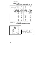
Page 4: ...5 368 38 daN 24 5 kg Adjustable 25 413 40 daN 34 5 kg Adjustable 58 470 40 daN 107 kg Adjustable Use temperatures Dimensions mm A B C D E F G H I J K L 0 C 50 C 547 627 371 451 131 200 115 55 206 25 90 93 130 368 574 0 C 50 C 582 642 371 451 134 196 120 55 233 25 90 93 170 413 646 0 C 50 C 930 1115 640 825 N A 330 226 90 233 58 90 160 270 470 703 Safety Devices In plant pre set limiter Control han...

Page 5: ...ing the toe or the head of the jack The 5 and 10 Ton jacks can be used either vertically or horizontally The 25 Ton Jack can be used only vertically The body can be positioned in relation to the toe and the base so as to be able to lift objects in restricted areas The toe must always be located above the base so that it can fold into it when the jack is closed see sketch 5 2 Operation Lifting Turn...

Page 6: ...ever lift up a load with the end of the toe or cause this situation after the toe has been moved The toe must be fully fitted in place and the thrust point of the load must never be further away from the barrel than the place where the logo is embossed on the toe Do not under any circumstances tamper with the adjustment of the jack s internal relief valve screw Do not add additional load to a lift...

Page 7: ... cracks Base deformation cracks In the event of doubt especially regarding cracks do not hesitate in replacing or carrying out any pertinent inspection to check the part All defective parts must be replaced and most of all not straightened out heated or welded Part replacement must be in accordance with the instructions given under disassembly assembly paragraph 6 3 6 2 Malfunction Failures FINDIN...

Page 8: ... 13 e Remove diaphragm 10 from the tank drain it and wipe it with a clean cloth only for 5t and 10t f Remove protector diaphragm C Column disassembly a Remove spring ring 3 using a pair of pliers Scrap it b Remove the column 2 toe 5 and guide 4 assembly from complete column 2 c Heat guide 4 200_C which was fitted with glue before unscrewing it d Remove toe 5 O rings 6 and seals 7 D Pump disassembl...

Page 9: ... 3 which before installation is in the shape of a straight wire with rounded ends curve it slightly and fit it through the rounded part on the edge of the slot made in jack body Hit the other end with a hammer while maintaining it firmly with pliers B Pump Assembly a Install seals 27 28 and beta pin 16 on sleeve 23 then lubricate the bore of the pump in which they are fitted Caution For the stage ...

Page 10: ...ball in using a rod Continue until the bubble escape by the bleed port k Tighten plug 33 on related sealing washer 47 D Final Assembly of the jack 25 t only a Position the jack vertically and hold the column in extended position b Fill the jack body through the top port c Tighten plug 8 on related seal 9 by the hand d Open the discharge valve e Lower the jack f Remove plug 8 and fill the jack with...

Page 11: ... bound to keep a maintenance log up to date Article R 233 12 in order to ensure operator safety 7 CHECKS STARTUP PERIODIC These checks are mandatory in all countries in EEC In France decree 93 41 Users dated 11 01 93 and law dated 9 06 93 set down the conditions Other texts laws or decrees passed or to be passed since the printing of these instructions will supersede the former mentioned 8 SCRAPPI...

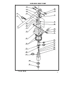
Page 12: ...DISCHARGE VALVE 5 Ton Plan No 28625 10 Ton Plan No 28626 12 ...

Page 13: ...EXPLODED VIEW PUMP Plan No 28086 13 ...

Page 14: ...EXPLODED VIEW 5t AND 10t TOE JACKS 14 5t Plan No 28625 10t Plan No 28626 Plan No 28086 ...

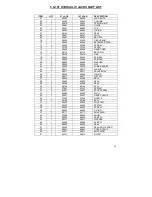
Page 15: ... 21 3 60046 60046 NUT 22 1 28508 28508 PUMP BARREL 23 1 28513 28513 SLEEVE 24 1 28511 28511 VALVE BODY 25 1 60654 60654 O RING 26 1 28477 28477 PISTON 27 1 60294 60294 SEAL 28 1 60582 60582 SEAL 29 2 60295 60295 SEAL 30 3 60164 60164 BALL 31 2 27047 27047 SPRING 32 2 25627 25627 STOP SCREW 33 2 28089 28089 PLUG 34 1 25631 25631 RELIEF VALVE 35 1 27592 27592 NOZZLE 36 1 60169 60169 BALL 37 1 25633 ...

Page 16: ...Exploded View 25t Toe Jack Plan No 28790 06 16 ...

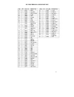
Page 17: ...54 O RING 26 1 28801 PISTON 27 1 60294 SEAL 28 1 60662 SEAL 29 2 60295 SEAL 30 3 60164 BALL 31 3 27047 SPRING 32 2 25627 STOP SCREW 33 2 30607 SHUTTLE 34 1 25631 RELIEF VALVE 35 1 27592 NOZZLE 36 1 60169 BALL 37 1 25633 SHUTTER 38 1 25632 SPRING 39 1 60602 SCREW 40 1 60660 O RING 41 1 60171 SNAP RING ITEM QTY 25T JACK DESCRIPTION 42 1 25635 KNOB 43 1 60603 SCREW 44 1 28517 WASHER 45 1 60669 SCREW ...

Page 18: ...rovide reasonable and necessary maintenance while in the possession of the consumer WE SHALL NOT BE LIABLE FOR CONSEQUENTIAL DAMAGES OF ANY KIND including but not limited to consequential labor costs or transportation charges in connection with the replacement or repair of defective parts We make no warranty with respect to trade accessories They are subject to the warranties of their manufacturer...

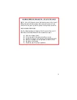
Page 19: ...sing faulty operation AIR PURGING PROCESS Use the following steps to bleed air from the jack in the event it has been accidentally lifted with the release valve open A Close the release valve B Pump the jack to full extension without a load C Loosen the plug 1 1 16 socket on the head of the jack D Allow air to bleed out until hydraulic oil starts to flow E Re tighten the fill plug F Check the jack...

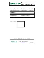
Page 20: ...NJ 07746 tel 732 462 6277 fax 732 462 6355 email sales hilmanrollers com Capacity Model Number Serial Number Manuf Date ____________________ ___________ _________ Inspected by ___________________________________ Inspection Date Inspector s Signature ____________ ______________________ Rev 05 01 30 2018 ...

Reviews: