background image


Network Microphone • User Manual 


Chapter 2 Installation and Application 

Installation 

Before you start 

Both ceiling and pendant mounting are suitable for the device. The supplied screws are for ceiling 
mounting. The bracket for pendant mounting shall be purchased separately. 


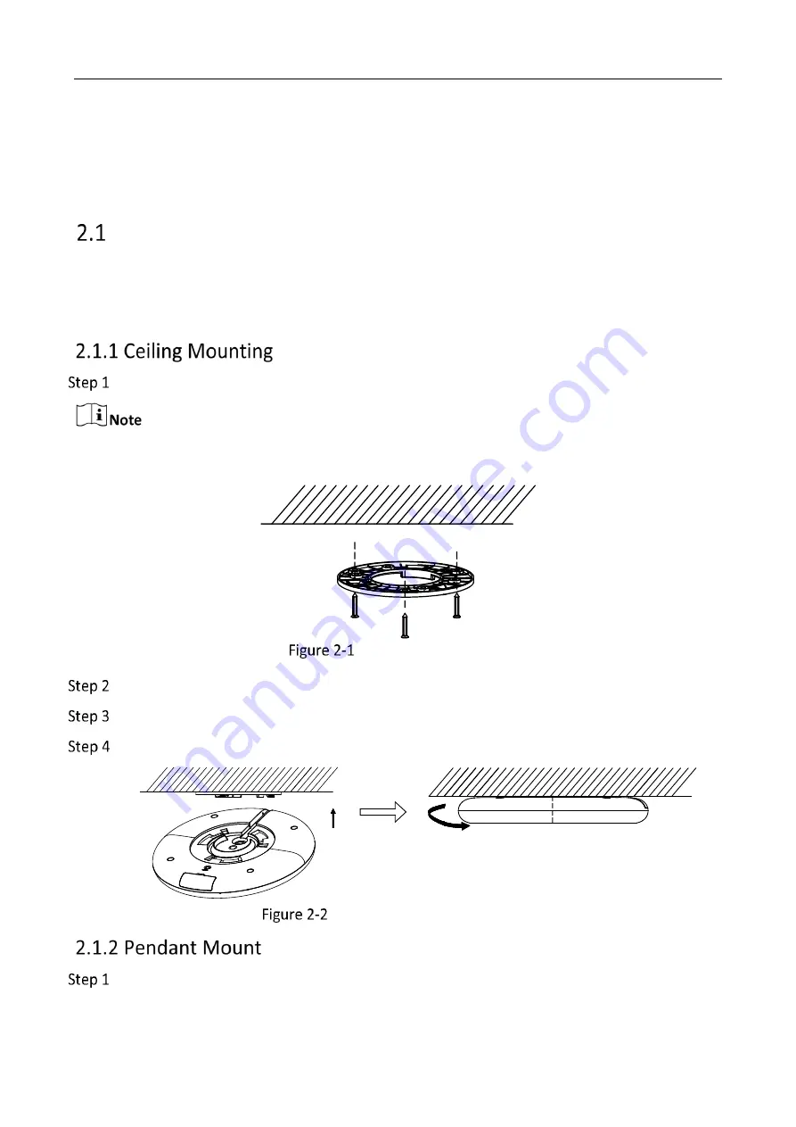
Fix the installation plate to the ceiling with three KA4 × 22 screws. 


(Optional) For cement wall, drill the screw holes with a 5.5 mm drill and insert the supplied wall 
plugs before installation. 


Fix the Installation Plate 


Remove the stick in the cable slot and snap the cable in the slot. 


Fit the microphone onto the installation plate. 


Turn the microphone as the figure below until it snaps into the installation plate. 


Install the Microphone to Ceiling 


Fix the bracket on the ceiling with four M6 metal expansion bolts. 

Summary of Contents for UD26182B

Page 1: ...Network Microphone User Manual...

Page 2: ...LUDING AMONG OTHERS DAMAGES FOR LOSS OF BUSINESS PROFITS BUSINESS INTERRUPTION OR LOSS OF DATA CORRUPTION OF SYSTEMS OR LOSS OF DOCUMENTATION WHETHER BASED ON BREACH OF CONTRACT TORT INCLUDING NEGLIGE...

Page 3: ...undesired operation EU Conformity Statement This product and if applicable the supplied accessories too are marked with CE and comply therefore with the applicable harmonized European standards listed...

Page 4: ...by unauthorized repair or maintenance Installation Install the equipment according to the instructions in this manual To prevent injury this equipment must be securely attached to the floor wall in ac...

Page 5: ...Activate Device 8 3 2 1 Activate Device via Web Browser 8 Access Device via Web Browser 9 3 3 1 Plug in Installation 9 Live View 9 Storage Settings 9 3 5 1 eMMC 9 3 5 2 Memory Card 10 Audio Settings 1...

Page 6: ...nce signal via line in interface and with AEC algorithm the microphone suppresses echo effectively Supports 5 level noise reduction and auto noise reduction avoiding environmental noise The indicator...

Page 7: ...nt Microphone 1 User Manual 1 Screws 1 Installation Plate 1 Appearance and Interfaces DC12VI N Indicator Line out Power Cord Network Cable Installation Plate Reset Type I Indicator Line out Power Cord...

Page 8: ...w Camera Power Cord Line out DC VI N G LI N E_OUT G OUT OUT Network Cable Education Sharing System Using Scenario I Connect the device with the camera Power Adapter Camera Network Cable Power Cord Lin...

Page 9: ...haring System Camera Microphone Power Cord Network Cable Using Scenario III Type II microphone can also directly connect to the education sharing system Refer to Figure 1 3 for detailed information If...

Page 10: ...plate to the ceiling with three KA4 22 screws Optional For cement wall drill the screw holes with a 5 5 mm drill and insert the supplied wall plugs before installation Fix the Installation Plate Remo...

Page 11: ...User Manual 6 Fix the Bracket Fix the installation plate to the bracket with four SC KM4 8 screws Fix the Installation Plate Refer to steps 2 to 3 of 2 1 1 Ceiling Mounting to finish installation Inst...

Page 12: ...commended to use an external linear regulated power supply The audio cable length should be shorter than 30 meters Indicator Status Description Solution No Light No Power Change the power adapter and...

Page 13: ...fore You Start Make sure your device and your PC connect to the same LAN Steps 1 Change the IP address of your PC to the same subnet as the device The default IP address of the device is 192 168 1 64...

Page 14: ...rowser Operation Windows Internet Explorer 10 Follow pop up prompts to complete plug in installation Google Chrome 57 Mozilla Firefox 52 Click to download and install plug in Live View It introduces t...

Page 15: ...vice For detailed installation refer to Quick Start Guide of the device If the memory card status is abnormal or the card does not match the file system the device only supports the memory card in FAT...

Page 16: ...e scenes can be set You can quick select the set scene according to the actual environment and slightly adjust the parameters Steps 1 Go to Configuration Audio Parameter Settings Advanced Settings 2 S...

Page 17: ...otocol Manual You can set the device IPv4 parameters manually Input IPv4 Address IPv4 Subnet Mask and IPv4 Default Gateway and click Test to see if the IP address is available The device port can be m...

Page 18: ...settings Default Reset all the parameters to the factory default Note Be careful when using this function After resetting to the factory default all the parameters cannot be recovered It helps speed...

Page 19: ...nd date of the device by configuring time zone and time synchronization Synchronize Time Manually Steps 1 Go to Configuration System System Settings Time Settings 2 Select Time Zone 3 Click Manual Tim...

Page 20: ...es over an unsecured network Go to Security and Maintenance Maintenance Debug Device to enable the function Caution Use the function with caution The security risk of device internal information leaka...

Page 21: ...e other accounts and grant different permission to different user levels Caution To increase security of using the device on the network please change the password of your account regularly Changing t...

Page 22: ...und Answers Check if the cables are connected correctly Poor quality of the cable and the cable connector may cause poor sound quality such as low sound and high noise Solution Connect the device shel...

Page 23: ...Multi Mic Array Microphone User Manual 18 camera Test before using the audio function If there is sound when testing check if the recording function is normal...

Page 24: ...UD26182B...

Reviews: