Network Dome Camera
·
Quick Start Guide
9
1
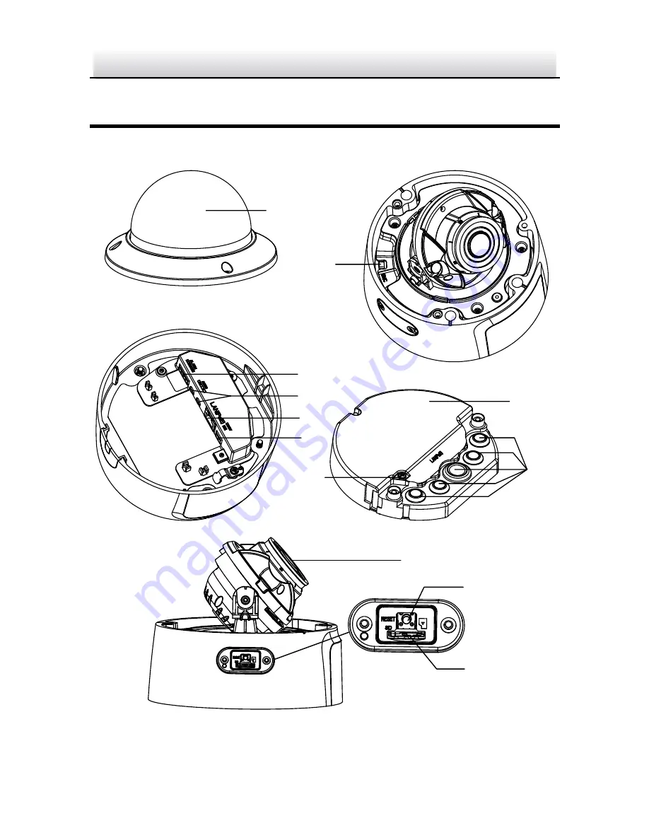
Appearance Description
The overview of the network dome camera is shown below.
2
3
4
5
6
7
8
12
10
11
Figure 1-1
Overview of Dome Camera
Page 1: ...1 Network Dome Camera Quick Start Guide UD05590B ...
Page 2: ...s guarantees or representations express or implied regarding to the Manual About this Manual This manual is applicable to Network Dome Camera The Manual includes instructions for using and managing the product Pictures charts images and all other information hereinafter are for description and explanation only The information contained in the Manual is subject to change without notice due to firmw...
Page 3: ...FITS BUSINESS INTERRUPTION OR LOSS OF DATA OR DOCUMENTATION IN CONNECTION WITH THE USE OF THIS PRODUCT EVEN IF HIKVISION HAS BEEN ADVISED OF THE POSSIBILITY OF SUCH DAMAGES REGARDING TO THE PRODUCT WITH INTERNET ACCESS THE USE OF PRODUCT SHALL BE WHOLLY AT YOUR OWN RISKS HIKVISION SHALL NOT TAKE ANY RESPONSIBILITES FOR ABNORMAL OPERATION PRIVACY LEAKAGE OR OTHER DAMAGES RESULTING FROM CYBER ATTACK...
Page 4: ...his equipment generates uses and can radiate radio frequency energy and if not installed and used in accordance with the instructions may cause harmful interference to radio communications However there is no guarantee that interference will not occur in a particular installation If this equipment does cause harmful interference to radio or television reception which can be determined by turning t...
Page 5: ...rective Products marked with this symbol cannot be disposed of as unsorted municipal waste in the European Union For proper recycling return this product to your local supplier upon the purchase of equivalent new equipment or dispose of it at designated collection points For more information see www recyclethis info 2006 66 EC battery directive This product contains a battery that cannot be dispos...
Page 6: ...any of the warnings are neglected Cautions Injury or equipment damage may occur if any of the cautions are neglected Warnings Proper configuration of all passwords and other security settings is the responsibility of the installer and or end user In the use of the product you must be in strict compliance with the electrical safety regulations of the nation and region Please refer to technical spec...
Page 7: ...l be firmly fixed If smoke odor or noise rise from the device turn off the power at once and unplug the power cable and then please contact the service center Cautions Make sure the power supply voltage is correct before using the camera Do not drop the camera or subject it to physical shock Do not touch sensor modules with fingers If cleaning is necessary use clean cloth with a bit of ethanol and...
Page 8: ... packing of the same texture Regular part replacement a few parts e g electrolytic capacitor of the equipment shall be replaced regularly according to their average enduring time The average time varies because of differences between operating environment and using history so regular checking is recommended for all the users Please contact with your dealer for more details Improper use or replacem...
Page 9: ...over the LAN 23 Wiring 23 3 1 Activating the Camera 24 3 2 Activation via Web Browser 24 3 2 1 Activation via SADP Software 25 3 2 2 Modifying the IP Address 27 3 3 4 Accessing via Web Browser 30 5 Operating via Hik Connect App 32 5 1 Enable Hik Connect Service on Camera 32 Enable Hik Connect Service via SADP Software 32 5 1 1 Enable Hik Connect Service via Web Browser 33 5 1 2 5 2 Hik Connect Set...
Page 10: ...Network Dome Camera Quick Start Guide 9 1 Appearance Description The overview of the network dome camera is shown below 1 2 3 4 5 6 7 8 12 9 10 11 Figure 1 1 Overview of Dome Camera ...
Page 11: ...ut output 9 Lens 4 RJ45 Ethernet port PoE 10 Reset button 5 Power interface 12 VDC 11 Memory card slot 6 Video Out BNC 12 Grounding screw Notes Reset button operation Press Reset button for about 10 s when the camera is powering on or rebooting to restore the default settings including the user name password IP address port No etc Standard power supply is 12 VDC or PoE 802 3af ...
Page 12: ...mera that supports IR you are required to pay attention to the following precautions to prevent IR reflection Dust or grease on the dome cover will cause IR reflection Please do not remove the dome cover film until the installation is finished If there is dust or grease on the dome cover clean the dome cover with clean soft cloth and isopropyl alcohol Make sure that there is no reflective surface ...
Page 13: ... card slot cover Cover Memory Card Install Memory Card Figure 2 1 2 Insert the memory card into the memory card slot and push to get it mounted 3 Optional To unmount the memory card push to eject it 4 Screw the cover back Mounting Preparation 2 2 Purpose Disassemble the camera for camera mounting ...
Page 14: ...rt Guide 13 Steps 1 Lift the camera body to separate the junction box and the adapter plate 2 Separate the junction box and the adapter plate 3 Unscrew the bubble Bubble Junction Box Adapter Plate Disassemble the Camera Figure 2 2 ...
Page 15: ...rough the ceiling and through side outlet Through the ceiling you should cut a hole in ceiling and route the cables in advance Through side outlet you choose to route cables with or without a conduit Steps 1 Mark 4 screw holes at desired mounting location according to No 2 screw holes on the adapter plate 46 1 81 6 Ø4 5 0 18 Ø140 5 51 31 5 1 24 Ø45 1 77 83 5 3 29 Adapter Plate Figure 2 3 ...
Page 16: ...ied Connect the Conduit Joint to Conduit Figure 2 4 2 Fit the adapter plate into the conduit joint Install the Conduit Figure 2 5 3 Secure the adapter plate to the ceiling with four supplied screws Note Use expansion screws for cement ceiling and self tapping screws for wooden ceiling 4 Route the cables through the junction box 1 Pierce the sealing plugs on junction box ...
Page 17: ...d cables through the sealing plugs Note For RJ45 network interface use supplied cable routing tool Cable Routing Tool Sealing Plug Route RJ45 Network Interface through Sealing Plug Figure 2 6 Junction Box Route Cables through Junction Box Figure 2 7 ...
Page 18: ... on junction box and adapter plate Secure the junction box to adapter plate with three screws Safety Rope Install Junction Box Figure 2 8 6 Hang the camera body on the safety rope 7 Connect the cables to correspondent plugs on camera bottom Connect Cables Figure 2 9 ...
Page 19: ... Fix the camera body to the junction box with three screws Fix the Camera Body Figure 2 10 9 Adjust surveillance angle 1 Use supplied BNC video out cable to connect the camera to a monitor Power on the camera to obtain live image of the camera ...
Page 20: ...uick Start Guide 19 Video Out BNC To Monitor Connect Video Out Figure 2 11 2 Hold the lens to adjust the panning tilting and rotating position Pan 0 to 355 Rotate 0 to 355 Tilt 0 to 75 Adjust Surveillance Angle Figure 2 12 ...
Page 21: ...g bracket shown below is only for demonstration Note When choosing a wall mounting bracket you must pay attention to the size of the cap which should match the adapter plate of the camera See Figure 2 3 Steps 1 Route the cables and install the wall mounting bracket 2 Install the cap to the bracket Secure the cap with a fixing screw Wall Mounting Bracket Cap Install Wall Mounting Bracket Figure 2 1...
Page 22: ... Mounting Before you start Pendant mounting bracket is not included in package If you choose this mounting type you have to prepare a bracket first The pendant mounting bracket shown below is only for demonstration Note When choosing a pendant mounting bracket you must pay attention to the size of the cap which should match the adapter plate of the camera See Figure 2 3 Steps 1 Route the cables an...
Page 23: ...igure 2 15 3 Align the screw holes of the adapter plate with the correspondent screw holes of the cap 4 Route the cables through the cable hole on adapter plate and secure the adapter plate to the cap 5 Repeat step 4 to step 10 of Section 2 3 1 Ceiling Mounting to complete camera installation ...
Page 24: ...tacks and information leakage please strengthen your own protection If the product does not work properly contact your dealer or the nearest service center for help Wiring 3 1 Connect the camera to network according to the following figures 半球 Network Cable or Network Camera Computer Connecting Directly Figure 3 1 网络交换机 半球 Network Cable Network Cable or or Network Camera Computer Connecting via a ...
Page 25: ...amera activation Note Refer to the User Manual of Network Camera for Activation via Client Software Activation via Web Browser 3 2 1 Steps 1 Power on the camera Connect the camera to your computer or the switch router which your computer connects to 2 Input the IP address into the address bar of the web browser and press Enter to enter the activation interface Notes The default IP address of the c...
Page 26: ...letters lower case letters numbers and special characters in order to increase the security of your product And we recommend you reset your password regularly especially in the high security system resetting the password monthly or weekly can better protect your product 4 Confirm the password 5 Click OK to save the password and enter the live view interface Activation via SADP Software 3 2 2 SADP ...
Page 27: ... Run the SADP software to search the online devices 2 Check the device status from the device list and select the inactive device Select inactive device Input and confirm password SADP Interface Figure 3 4 Note The SADP software supports activating the camera in batch Refer to the user manual of SADP software for details 3 Create and input the new password in the password field and confirm the pas...
Page 28: ...evice during activation Refer to Chapter 5 1 for detailed information 4 Click Activate to start activation You can check whether the activation is completed on the popup window If activation failed make sure that the password meets the requirement and try again Modifying the IP Address 3 3 Purpose To view and configure the camera via LAN Local Area Network you need to connect the network camera in...
Page 29: ... Steps 1 Run the SADP software 2 Select an active device 3 Change the device IP address to the same subnet with your computer by either modifying the IP address manually or checking the checkbox of Enable DHCP Modify the IP Address Figure 3 5 ...
Page 30: ...t service for the device during activation Refer to Chapter 5 1 for detailed information 4 Input the admin password and click Modify to activate your IP address modification The batch IP address modification is supported by the SADP Refer to the user manual of SADP for details ...
Page 31: ...he web browser 2 In the browser address bar input the IP address of the network camera and press the Enter key to enter the login interface Note The default IP address is 192 168 1 64 You are recommended to change the IP address to the same subnet with your computer 3 Input the user name and password The admin user should configure the device accounts and user operator permissions properly Delete ...
Page 32: ...w the installation prompts to install the plug in Note You may have to close the web browser to finish the installation of the plug in Download Plug in Figure 4 2 6 Reopen the web browser after the installation of the plug in and repeat steps 2 to 4 to login Note For detailed instructions of further configuration please refer to the user manual of network camera ...
Page 33: ...onnect Service on Camera Purpose Hik Connect service should be enabled on your camera before you using the service You can enable the service through SADP software or web browser Enable Hik Connect Service via SADP Software 5 1 1 Steps 1 Check the checkbox of Enable Hik Connect on 1 Activate the Device page during camera activation refer to Chapter 3 2 2 2 Or Modify Network Parameters page during ...
Page 34: ...erification code is required when you add the camera to Hik Connect app 3 Click and read Terms of Service and Privacy Policy 4 Confirm the settings Enable Hik Connect Service via Web Browser 5 1 2 Before you start You need to activate the camera before enabling the service Refer to Chapter 3 2 ...
Page 35: ...ngs Platform Access Platform Access Configuration Web Figure 5 2 3 Select Platform Access Mode as Hik Connect 4 Check the checkbox of Enable 5 Click and read Terms of Service and Privacy Policy in pop up window 6 Create a verification code or change the verification code for the camera Note The verification code is required when you add the camera to Hik Connect app 7 Save the settings ...
Page 36: ...t Before you start You need to enable the Hik Connect service on camera before adding it to your Hik Connect account Refer to Chapter 5 1 Steps 1 Use a network cable to connect the camera with a router if the camera does not support Wi Fi Figure 5 3 Connect a Router Note After the camera connects to the network please wait one minute before any operation on the camera using Hik Connect app 2 In th...
Page 37: ...the camera s serial number 3 Input the verification code of your camera Note The required verification code is the code you create or change when you enabling Hik Connect service on camera If you forget the verification code you can check the current verification code on Platform Access configuration page via web browser 4 Follow the prompts to set the network connection and add the camera to your...
Page 38: ... memory card status by tapping on the Storage Status in the Device Settings interface If the memory card status displays as Uninitialized tap to initialize it The status will then change to Normal You can then start recording any event triggered video in the camera such as motion detection ...
Page 39: ...Network Dome Camera Quick Start Guide 38 ...