HIKVISION UD.6L0201D1633A01 User Manual Download Page 28

HD WDR Box Camera

·

User Manual


27 

27 

The gain of BLC can be set to 

High

Middle

, and 

Low

, the higher the 

gain is, and the clearer the image is. Follow the steps below to set a 
BLC area. 

Steps: 

1.


Move the cursor 

AREA

, and press 

OK

 to enter the area edit 

interface. 

2.


Move the joystick up/down/left/right to define the BLC position. 

3.


Press 

OK

 to enter the area size edit interface. 

4.


Move the joystick up/down/left/right to define the BLC size. 

5.


Press 

OK

 to confirm the selection, and select 

RET 

to go back the 

BLC menu, or select 

AGAIN 

to re-define the BLC area. 

6.


(Optional) Move the cursor to 

DEFAULT

 and press 

OK

 to restore 

the BLC settings to the default. 
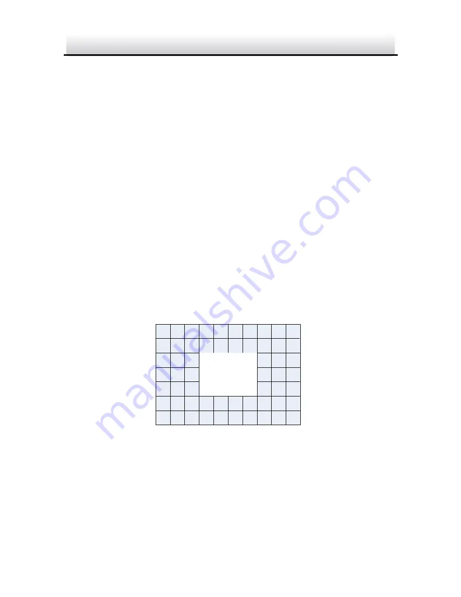
 POSITION


Define a BLC Area 

Figure 3-5

Summary of Contents for UD.6L0201D1633A01

Page 1: ...0 Camera User Manual HD WDR Box Camera UD 6L0201D1633A01...

Page 2: ...n the manual This manual applies to the DS 2CC12D9T A DISCLAIMER STATEMENT Underwriters Laboratories Inc UL has not tested the performance or reliability of the security or signaling aspects of this p...

Page 3: ...tions Operation of this equipment in a residential area is likely to cause harmful interference in which case the users will be required to correct the interference at their own expense FCC Conditions...

Page 4: ...e of equivalent new equipment or dispose of it at designated collection points For more information see www recyclethis info 2006 66 EC battery directive This product contains a battery that cannot be...

Page 5: ...nt damage may occur if any of the cautions are neglected Warnings In the use of the product you must be in strict compliance with the electrical safety regulations of the nation and region Please refe...

Page 6: ...he power cable and then please contact the service center If the product does not work properly please contact your dealer or the nearest service center Never attempt to disassemble the camera yoursel...

Page 7: ...ra in extremely hot cold the operating temperature shall be 10 60 dusty or damp locations and do not expose it to high electromagnetic radiation To avoid heat accumulation good ventilation is required...

Page 8: ...nstallation 12 Wall Mounting 12 2 1 Ceiling Mounting 18 2 2 3 Menu Description 20 3 1 VIDEO OUT 21 3 2 LANGUAGE 21 3 3 SETUP 21 3 3 1 SMART FOCUS 21 3 3 2 SCENE 21 3 3 3 LENS 22 3 3 4 EXPOSURE 22 3 3...

Page 9: ...ance system and image process system Main Features Adopt high performance CMOS and supply high definition and clear image Low illumination 0 01Lux F1 2 AGC ON 0Lux with IR Support ICR infrared filter...

Page 10: ...of the Box Camera Figure 1 1 Table 1 1 Description of the Box Camera No Description 1 Lock screw 2 Auto Iris Drive Interface The Auto Iris Interface The auto iris interface is composed of four square...

Page 11: ...Manual 10 No DC 1 Damp 2 Damp 3 Driver 4 Driver Pins of the Auto Iris Interface Figure 1 2 Rear Panel The rear panel of the box camera is shown as follows 3 4 5 6 7 9 8 3 1 2 Panel Description of the...

Page 12: ...able 1 2 The Rear Panel Description No Description No Description 1 Lens 6 Power Indicator 2 Mic 7 Grounding Screw 3 Analog Video Output Interface 8 Power Interface 4 TVI Video Output Interface 9 Alar...

Page 13: ...to avoid damage Please make sure the wall or ceiling is strong enough to withstand three times the weight of the camera and the mounting If the wall or ceiling is built by cement you need to insert e...

Page 14: ...lens The weight of the lens must be less than 1kg It s better to install a lens with CS type interface If the interface of lens is C type you need to install a C adaptor between the lens and the camer...

Page 15: ...the Back plane in the housing Figure 2 2 4 Fix the back plane with the camera in the camera housing As shown in Figure 2 3 Fix the Camera in the Housing Figure 2 3 5 Adjust the focal length of the le...

Page 16: ...according to the size of the sensor The automatic iris lens will work at the maximum aperture mode 6 Connect the camera with corresponding cables and route the cables through the cable hole on the bot...

Page 17: ...acket Figure 2 5 The wall mount not provided should be longer than 1 2 of the camera length 9 Attach the camera with the housing to the wall mount and tighten the fix screw to fix the camera As shown...

Page 18: ...g lock screw to adjust the panning angle of the camera As shown in Figure 2 7 Adjust the Panning Angle Figure 2 7 11 Loosen the tilting lock screw You can adjust the tilting angle of the camera As sho...

Page 19: ...the drill template As shown in Figure 2 9 Mounting Template Figure 2 9 2 Attach the ceiling mount to the wall and tighten the screws to fix it As shown in Figure 2 10 Install the Bracket Figure 2 10...

Page 20: ...HD WDR Box Camera User Manual 19 Fix the Camera Housing Figure 2 11 4 Loosen the adjustable nut to adjust the panning angle and tilt angle of the camera Adjustment Nut Angle Adjustment Figure 2 12...

Page 21: ...NR CAM TITLE D EFFECT MOTION PRIVACY LAUGUAGE DEFECT RS485 SHARPNESS MONITOR LSC VIDEO OUT EXIT SETUP DC AUTO WDR Main Menu Overview Figure 3 1 This series of camera adopts a joystick to select the me...

Page 22: ...lect the required video output standard 3 2 LANGUAGE This series of camera supports multiple languages English Japanese CHN1 CHN2 Korean German French Italian Spanish Polish Russian Portuguese Dutch T...

Page 23: ...NESS 40 5 D WDR OFF 6 DEFOG OFF 7 RETURN RET Exposure Figure 3 2 Exposure describes the brightness related parameters You can adjust the image brightness by the SHUTTER AGC SENS UP BRIGHTNESS ACCE BAC...

Page 24: ...the clarity of image in poor light scene You can set the AGC value from 1 to 15 The noise will be amplified if the AGC is on SENS UP If you select shutter as AUTO or 1 30 the SENS UP is adjustable OF...

Page 25: ...e both very bright and very dark areas simultaneously in the field of view D WDR balances the brightness level of the whole image and provide clear images with details Set the D WDR to ON to improve t...

Page 26: ...efine the position of the defog area 3 Press OK again to switch the position configuration to the size configuration 4 Move the joystick up down right left to define the size of the defog area 5 Press...

Page 27: ...h luminance environment you can set the Backlight to OFF BLC WDR and HSBLC Backlight Compensation BLC If there s a strong backlight the object in front of the backlight will appear silhouetted or dark...

Page 28: ...it interface 2 Move the joystick up down left right to define the BLC position 3 Press OK to enter the area size edit interface 4 Move the joystick up down left right to define the BLC size 5 Press OK...

Page 29: ...Set the cursor right left to select HSBLC and press OK to enter the edit interface 2 Move the cursor to SELECT and select the area by setting the joystick to left right Four areas are selectable 3 Se...

Page 30: ...nly when the Black Mask is set as ON the HSBLC takes effect If you the set black mask as OFF the HSBLC function is disabled DEFAULT Selecting DEFAULT will restore all the HSBLC settings to the default...

Page 31: ...the white balance by customizing the Blue and Red value which range from 1 to 100 MANUAL WB BLUE 51 RED 50 RETURN RET Manual White Balance Figure 3 7 ATW ATW mode refers to the white balance is contin...

Page 32: ...utomatically according to the light condition AUTO The image switches from color to B W or from B W to color automatically by comparing the configured threshold value with actual light condition Delay...

Page 33: ...LAY 8 0 2 D N AGC 8 0 3 N D AGC 8 0 4 RETURN RET Auto Figure 3 8 3 3 8 NR NR Noise Reduction is used to reduce the noise in the video stream Move the cursor to NR and press OK to enter the NR submenu...

Page 34: ...mages in low light conditions and delivering more accurate and sharp image quality 3D NR 1 SMART NR ON 2 LEVEL 8 0 3 START AGC 10 4 END AGC 10 5 RETURN RET 3D NR Figure 3 10 Smart NR usually takes eff...

Page 35: ...age the motion detection privacy task language dead pixel correction and check the version of the camera SPECIAL 1 CAM TITLE ON 2 D EFFECT 3 MOTION OFF 4 PRIVACY OFF 5 DEFECT 6 RS485 7 RETURN RET Spec...

Page 36: ...cursor to select the needed characters numbers and symbols 3 Press OK to confirm The selected character will be displayed on the dotted line below 4 Move the cursor to POS to edit the camera title po...

Page 37: ...ZE OFF 2 MIRROR OFF 3 D ZOOM OFF 4 SMART D ZOOM OFF 5 NEG IMAGE OFF 6 RETURN RET D effect Figure 3 14 FREEZE You can set the freeze function as ON or OFF When you set it as on the image is frozen as s...

Page 38: ...be enlarged without gaining the actual pixel D ZOOM 1 D ZOOM x 2 0 2 PAN TILT 3 DEFAULT 4 RETURN RET D Zoom Figure 3 15 The minimum magnification is x2 and the maximum magnification is x62 You can def...

Page 39: ...to display not display the smart D Zoom area And if the display is set to ON press OK to enter the position edit interface and define the smart D Zoom area The sensitivity ranges from 0 to 60 The hig...

Page 40: ...ted and the alarm will be triggered MOTION 1 SELECT AREA 1 2 DISPLAY ON 3 SENSITIVITY 30 4 MOTION VIEW ON 5 DEFAULT 6 RETURN RET Motion Detection Figure 3 17 Set a Motion Detection Area Steps 1 Move t...

Page 41: ...to the default SENSITIVITY It refers to the sensitivity of the motion detection which ranges from 0 to 60 And the higher sensitivity causes the better response of the detection MOTION VIEW Motion vie...

Page 42: ...acy mask area Eight areas are selectable 2 Move the cursor to DISPLAY and press OK to enter the privacy mask edit interface INV mosaic color and off are selectable for display INV The privacy mask are...

Page 43: ...bottom right of the selected area 5 Press OK to confirm the configuration and select RET to return to the privacy mask menu or select AGAIN to try again 6 Optional Move the cursor to DEFAULT and pres...

Page 44: ...AUTO is selectable The correction level 0 255 is configurable if the live DPC is set to ON set it OFF to disable the live defective pixel correction and set it AUTO to detect and repair the defective...

Page 45: ...level of the STATIC DPC ranges from 0 to 60 Some of the defective pixels may appear undistinguished for the system to detect You can adjust the SENS UP to X2 X4 X6 X8 X10 X15 X20 X25 or X30 to bright...

Page 46: ...guration interface ADJUST 1 SHARPNESS 15 2 MONITOR LCD 3 LSC OFF 4 RETURN RET Adjust Figure 3 22 Sharpness Sharpness determines the amount of detail an imaging system can reproduce And you can adjust...

Page 47: ...n user define the gamma blue gain 0 100 and red gain 0 100 Gamma is the name of a nonlinear operation used to code and decode luminance or tristimulus values in video or still image system USER Y USER...

Page 48: ...LSC corrects the phenomenon where the image gets darkened or blurred on the periphery Set it ON to enable the LSC Set it OFF to disable the LSC 3 3 11 RESET Reset all the settings to the default 3 3 1...

Page 49: ...HD WDR Box Camera User Manual 48...

Reviews: