HIKVISION iDS-9600NXI-I16/16SB Series Quick Start Manual Download Page 31

Network Video Recorder Quick Start Guide 

30 

2.2.2 iDS-7700NXI-I4/(16P)/16S(B), iDS-7600NXI-I2/8F and 
iDS-7600NXI-I2/P/8F Series 

Purpose: 

The following section introduces the HDD installation. 

Before you start: 


Ensure power is disconnected.   


Prepare a factory recommended HDD, and cross screwdriver. 
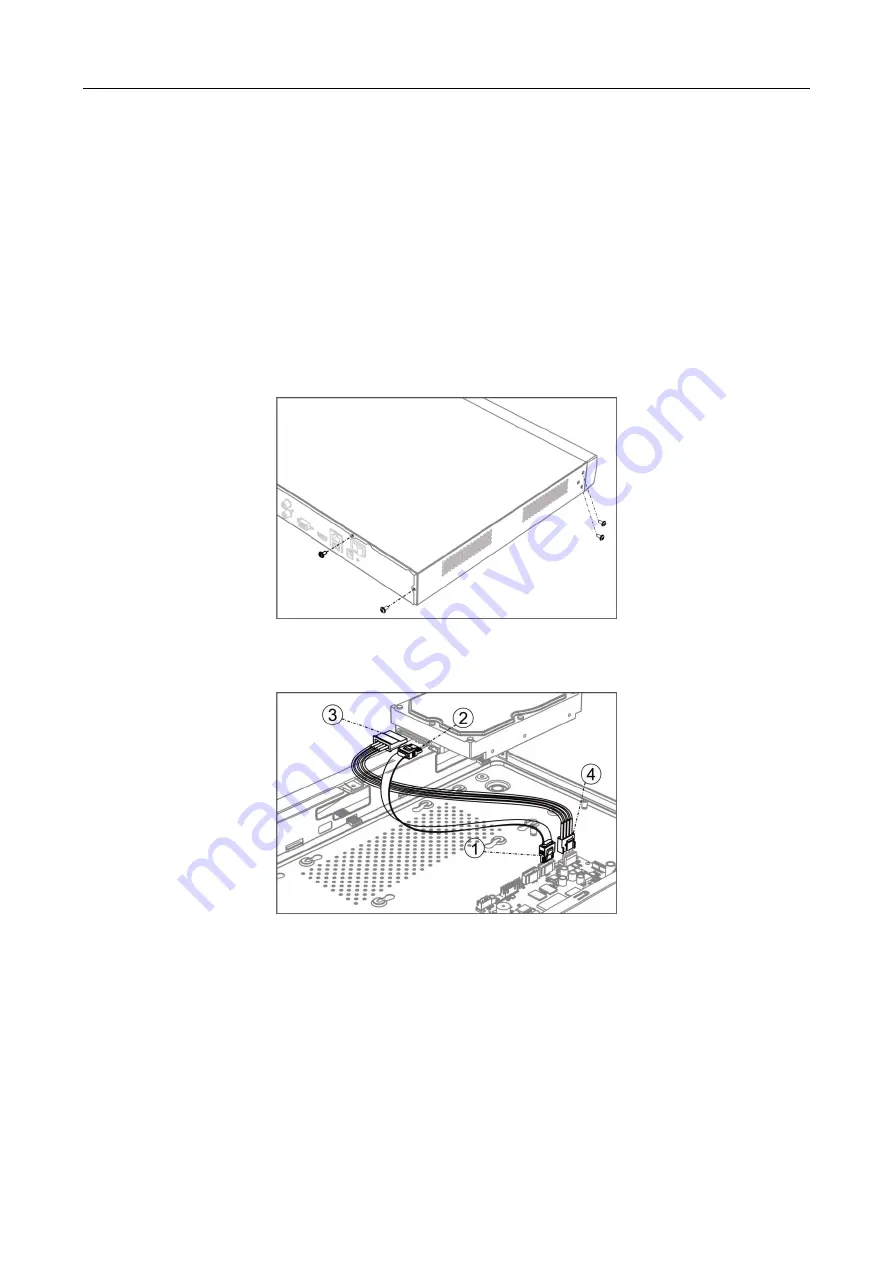
Step 1


Unfasten screws on each panel to remove the device cover. 


Figure 2-8


Remove Cover 

Step 2


Connect the data cable and power cable. 


Figure 2-9


Connect Cable 

Step 3


Match HDD screw threads with the reserved holes on the device bottom, and fix HDD with 
screws. 

Summary of Contents for iDS-9600NXI-I16/16SB Series

Page 1: ...Network Video Recorder Quick Start Guide...

Page 2: ...1 2 4 iDS 7700NXI I4 16P 16S B Series 20 1 2 5 iDS 7600NXI I2 8F and iDS 7600NXI I2 P 8F Series 22 1 2 6 iDS 6700NXI I 16S B and iDS 6700NXI I 8F B Series 23 1 2 7 iDS 9600NXI I8 4F B 25 Chapter 2 In...

Page 3: ...Network Video Recorder Quick Start Guide 2 Chapter 4 Face Picture Comparison 46 Chapter 5 Access by Web Browser 47...

Page 4: ...gos mentioned below are the properties of their respective owners Legal Disclaimer TO THE MAXIMUM EXTENT PERMITTED BY APPLICABLE LAW THE PRODUCT DESCRIBED WITH ITS HARDWARE SOFTWARE AND FIRMWARE IS PR...

Page 5: ...erence 2 This device must accept any interference received including interference that may cause undesired operation EU Conformity Statement This product and if applicable the supplied accessories too...

Page 6: ...I I24 G6 B iDS 96256NXI I24 G12 B iDS 9600NXI I8 8F B iDS 9616NXI I8 8F B iDS 9632NXI I8 8F B iDS 9664NXI I8 8F B iDS 9600NXI I8 16S B iDS 9616NXI I8 16S B iDS 9632NXI I8 16S B iDS 9664NXI I8 16S B iD...

Page 7: ...I I2 8P 8F iDS 7616NXI I2 16P 8F iDS 7632NXI I2 16P 8F iDS 7700NXI I4 16P 16S B iDS 7716NXI I4 16P 16S B iDS 7732NXI I4 16P 16S B iDS 7700NXI I4 16S B iDS 7716NXI I4 16S B iDS 7732NXI I4 16S B iDS 960...

Page 8: ...ly connected to the power socket If smoke odor or noise rise from the device turn off the power at once and unplug the power cable and then please contact the service center Preventive and Cautionary...

Page 9: ...evice Improper use or replacement of the battery may result in hazard of explosion Replace with the same or equivalent type only Dispose of used batteries according to the instructions provided by the...

Page 10: ...panel by the key 2 Power Button Turn on off device Solid blue Device is on Solid red Device is off 3 Mute Button Turn on off alarm beep Solid blue Alarm sound is off Unlit Alarm sound is on 4 HDD Ind...

Page 11: ...or unlocks the panel by the key 2 Power Button Turn on off device Solid blue Device is on Solid red Device is off 3 LCD 7 inch LCD for live view image and menu operation 4 HDD Sequence Indicator Shows...

Page 12: ...d when the power is connected but the system isn t running Turns blue when the power is connected and the system is running 2 Tx Rx Flickers blue when network connection is functioning properly 3 READ...

Page 13: ...D Solid red At least one HDD is installed Unlit No HDD is detected Flashing red HDD is reading writing Tx Rx Flashing blue indicates network communication is normal 4 Shortcut Button Exit Returns to t...

Page 14: ...in menus In the playback mode use the Up and Down buttons to speed up and slow down recorded video Use the Left and Right buttons to select the next and previous video files Cycles through channels i...

Page 15: ...ion Turns red when device is powered up Turns red when data is being read from or written to HDD Flickers blue when network connection is functioning properly 1 1 7 iDS 9600NXI I8 4F B Figure 1 7 Fron...

Page 16: ...one HDD is installed Unlit No HDD is detected Flashing red HDD is reading writing READY Turns blue when the device is functioning properly ARCHIVE Reserved Channel Status Indicator Blue indicates reco...

Page 17: ...rder Quick Start Guide 16 1 2 Rear Panel 1 2 1 iDS 96000NXI I16 24 B iDS 96000NXI I16 G B and iDS 96000NXI I24 G B Series Figure 1 8 iDS 96000NXI I16 B Series Rear Panel Figure 1 9 iDS 96000NXI I24 B...

Page 18: ...I1 HDMI2 HDMI video output connector 2 AUDIO OUT RCA connector for audio output 3 USB 3 0 Interface Universal Serial Bus USB interface for additional devices such as USB mouse and USB Hard Disk Drive...

Page 19: ...r for VGA output Display local video output and menu 15 RS 232 Interface Connector for RS 232 devices 16 Extension Board 4 RJ45 10 100 1000 Mbps self adaptive optical interfaces 8 RS 485 full duplex A...

Page 20: ...er For cascading devices the first NVR s D D pin should be connected with the D D pin of the next NVR ALARM IN Connector for alarm input ALARM OUT Connector for alarm output 10 Power Supply 100 to 240...

Page 21: ...l devices such as USB mouse and USB Hard Disk Drive HDD 7 RS 232 Interface Connector for RS 232 devices 8 eSATA Connects external SATA HDD CD DVD RM 9 Controller Port D D pin connects to Ta Tb pin of...

Page 22: ...and USB Hard Disk Drive HDD 6 RS 232 Interface Connector for RS 232 devices 7 VGA DB9 connector for VGA output Display local video output and menu 8 RS 485 Interface Half duplex connector for RS 485...

Page 23: ...VGA output Display local video output and menu 4 ALARM IN Connector for alarm input ALARM OUT Connector for alarm output 5 HDMI HDMI video output connector 6 USB Interface Universal Serial Bus USB in...

Page 24: ...audio input device or active pick up microphone etc 3 AUDIO OUT 3 5mm interface connect to audio output device e g loudspeaker etc 4 RS 232 Serial interface for configuration of device s parameters or...

Page 25: ...r Supply 12 VDC power supply 5 SW SW dial switch 6 USB 2 0 Interface Universal Serial Bus USB interface for additional devices such as USB mouse and USB Hard Disk Drive HDD 7 LAN1 LAN2 10 100 1000 Mbp...

Page 26: ...deo output connector 6 USB 3 0 Interface Universal Serial Bus USB interface for additional devices such as USB mouse and USB Hard Disk Drive HDD 7 eSATA Connects external SATA HDD CD DVD RM 8 SW SW di...

Page 27: ...ive pole to number 1 of Ctrl 12V and connect negative pole to G of Ctrl 12V 11 DC 12V 12 VDC 1 A power output for external device Connect positive pole to number 1 of DC 12V and connect negative pole...

Page 28: ...e between racks mounted devices Ensure the NVR is grounded Environmental temperature should be within the range of 10 C to 55 C 14 F to 131 F Environmental humidity should be within the range of 10 to...

Page 29: ...ng the direction arrow Handle with care to avoid damage Figure 2 2 Remove the Cover Step 3 Press the blue button to pop up the handle and hold the handle and pull the dummy HDD out of the slot Figure...

Page 30: ...Figure 2 5 Push the Dummy HDD into the Slot Step 6 Press the handle until you hear a click Thus to fix the dummy HDD Repeat above steps to install the rest dummy HDDs Figure 2 6 Press the Handle Step...

Page 31: ...installation Before you start Ensure power is disconnected Prepare a factory recommended HDD and cross screwdriver Step 1 Unfasten screws on each panel to remove the device cover Figure 2 8 Remove Cov...

Page 32: ...ect the power from the NVR before installing a hard disk drive HDD A factory recommended HDD should be used for this installation Tools Required Screwdriver Step 1 Fasten the hard disk mounting handle...

Page 33: ...stall other hard disks onto the NVR Step 6 After having finished the installation of all hard disks close the front panel and lock it with the key again 2 3 Connections 2 3 1 Alarm Input Wiring The al...

Page 34: ...igure above There are 4 jumpers JP6 JP9 JP10 and JP11 on the motherboard each corresponding with one alarm output By default jumpers are connected To connect an AC load jumpers should be removed Examp...

Page 35: ...signal cables into slots and fasten stop screws Ensure signal cables are in tight Step 4 Connect Ta on controller to D on terminal block and Tb on controller to D on terminal block Fasten stop screws...

Page 36: ...384K 168M 448K 196M 512K 225M 640K 281M 768K 337M 896K 393M 1024K 450M 1280K 562M 1536K 675M 1792K 787M 2048K 900M 4096K 1 8G 8192K 3 6G 16384K 7 2G Please note that supplied values for storage space...

Page 37: ...the POWER button on the front panel The Power LED should turn blue The unit will begin to start After the device starts up the wizard will guide you through the initial settings including modifying pa...

Page 38: ...ep 3 When the device is activated the system pops up the message box to remind you to properly keep the password And you can click OK to continue to export the GUID file for the future password resett...

Page 39: ...pattern is configured successfully If the two patterns are different you must set the pattern again 3 4 Log into the System Purpose If the device has logged out you must log in the device before opera...

Page 40: ...Enter Wizard to Configure Quick Basic Settings The Setup Wizard can walk you through some important settings of the device By default the Setup Wizard starts once the device has loaded Check the check...

Page 41: ...v4 Gateway MTU and DNS Server Step 4 If the DHCP server is available you can check the checkbox of DHCP to automatically obtain an IP address and other network settings from that server Step 5 After h...

Page 42: ...era to add Step 4 Enter the login user name and password of the IP camera Step 5 Click Add to finish the adding of the IP camera Step 6 Optional Click Continue to Add to continue to add other IP camer...

Page 43: ...the RAID storage function Through one touch configuration you can quickly create the disk array By default the array type to be created is RAID 5 Before you start Enable RAID function Install at leas...

Page 44: ...etup Array view the information of created arrray 3 10 Recording Settings Before you start Make sure that the disk has already been installed or added If not please install or add a disk and initializ...

Page 45: ...disk can be played back in the following modes instant playback all day playback for the specified channel and playback by normal important custom event smart tag sub periods external file search Step...

Page 46: ...Network Video Recorder Quick Start Guide 45 Figure 3 11 Playback Interface Step 4 Select the channel s to or execute simultaneous playback of multiple channels...

Page 47: ...0NXI I16 8F B iDS 9600NXI I8 8F B iDS 9600NXI I8 4F B iDS 96000NXI I16 G B and iDS 96000NXI I24 G B series Step 1 Go to Smart Analysis Face Picture Database Step 2 Add the face picture library to the...

Page 48: ...supported resolutions include 1024 768 and above Step 1 Open web browser input the IP address of the device and then press Enter Step 2 Login to the device If the device has not been activated you nee...

Page 49: ...in Step 3 Install the plug in before viewing the live video and managing the camera Please follow the installation prompts to install the plug in You may have to close the web browser to finish the in...

Page 50: ...UD14883B...

Reviews: