background image

ICVS User Manual 

19 


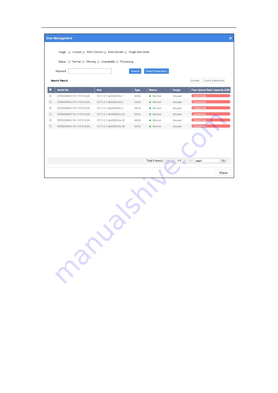
Figure 4-12


Disk Management 

Step 4


Specify search conditions. 


Usage


Unused: Disk not used by any RAID domain. 


Single Disk Mode: Reserved. 


When disk Usage is set as UnusedStatus description is shown as follows:   


Normal: Disk is normal in all online nodes. 


Warning: Disk is normal in some online nodes. Or bad sector exists in the 

disk. 


Unavailable: Disk is abnormal in all the online nodes. Disk will be removed 

from resource pool. 


Processing: Disk is being detected, located, repaired, moved, or maintained. 

Step 5


Click Search

When disk status is warning, unavailable, or processing, click the status in 
status column to show help. You can follow the help to recover disk. 

Step 6


Optionally, to locate a disk, check the disk and click Locate to turn on FN 
indicator of the disk. FN indicator will keep flashing (default flashing time is 600 
seconds). 

Step 7


Optionally, to detect a disk, check the disk and click Quick Detection. Detection 
progress will be shown in Status column. 

Summary of Contents for ICVS

Page 1: ...0 ICVS User Manual...

Page 2: ...Overview 14 4 3 2 Locate Device 14 4 3 3 Mute Device 15 4 3 4 Reboot and Shut down Device 15 4 3 5 More Operations 15 4 4 Device Graph of a Node 15 4 4 1 Device Indicator 15 4 4 2 HDD Slot Graph 16 4...

Page 3: ...er trademarks and logos mentioned below are the properties of their respective owners Legal Disclaimer TO THE MAXIMUM EXTENT PERMITTED BY APPLICABLE LAW THE PRODUCT DESCRIBED WITH ITS HARDWARE SOFTWAR...

Page 4: ...ICVS User Manual 3 IN THE EVENT OF ANY CONFLICTS BETWEEN THIS MANUAL AND THE APPLICABLE LAW THE LATER PREVAILS...

Page 5: ...cause harmful interference 2 This device must accept any interference received including interference that may cause undesired operation EU Conformity Statement This product and if applicable the sup...

Page 6: ...s Symbol Description Provides additional information to emphasize or supplement important points of the main text Indicates a potentially hazardous situation which if not avoided could result in equip...

Page 7: ...turn off the power at once and unplug the power cable and then please contact the service center Preventive and Cautionary Tips Before connecting and operating your device please be advised of the fol...

Page 8: ...computer IP address Ensure it is in the same network segment with the Management LAN of the device the default IP address of Management LAN is 10 254 254 254 Step 1 Enter the device IP address https...

Page 9: ...d you create a strong password of your own choosing Using a minimum of 8 characters including at least three of the following categories upper case letters lower case letters numbers and special chara...

Page 10: ...uration Figure 2 1 Shortcut Mute alarm sound for alarm events Only valid for current alarm events Show the exception alarm information You can search alarm information by specifying alarm level comput...

Page 11: ...ICVS User Manual 10 Figure 2 3 Change Password Log out system At next login you will automatically enter the page of last login...

Page 12: ...iption Writing reading performance Shows the time network bandwidth IOPS and writing reading size You can set the Performance Refresh Frequency and Computing Unit only available for dual controller de...

Page 13: ...ICVS User Manual 12 Figure 3 2 View CPU and Memory Performance...

Page 14: ...Figure 4 1 Node Tree 4 1 2 Map Step 1 Go to Device Step 2 Click a node in node tree to refresh the topological graph of network switch node and the topological graph of specified device Figure 4 2 Nod...

Page 15: ...vice Overview to view device name IP address port status etc Figure 4 4 Device Overview 4 3 2 Locate Device Purpose To find a device turn on FN indicator on its front panel Step 1 Check the device Ste...

Page 16: ...utdown Step 4 Enter Password and Verification Code to confirm the operation 4 3 5 More Operations Rename a device For details refer to Rename Device Modify device network parameters For details refer...

Page 17: ...No Description Normal Blue HDD detection is normal Warning Red HDD is not available instantly after HDD detection Only after repair can you decide if the HDD is normal or not Handling Light blue HDD i...

Page 18: ...on Locate Click it to turn on FN indicator of the selected HDD The indicator will keep flashing default flashing time is 600 seconds 4 4 3 Information Overview Purpose View environment and control inf...

Page 19: ...card CPU etc Fan Working status of chassis fan backboard fan and power fan Power Power module working status Figure 4 11 Information Overview Manage Disk Purpose You can search the information of all...

Page 20: ...online nodes Disk will be removed from resource pool Processing Disk is being detected located repaired moved or maintained Step 5 Click Search When disk status is warning unavailable or processing c...

Page 21: ...tion Overview Step 3 Click Device Rename Step 4 Enter New Name and click OK Device name must be unique in the domain Valid name contains 1 to 16 characters and only digits lowercase and uppercase are...

Page 22: ...to Device Step 2 Click Information Overview Step 3 Click Modify Network Step 4 Click Settings of a bound port Port Name Not editable Jumbo Frame Size Default value is 1500 Default value is recommended...

Page 23: ...port binding Connect all bound ports to network View Bound Port Attribute Purpose View bound port attribute including port name port attribute binding mode etc Step 1 Go to Device Step 2 Click Informa...

Page 24: ...ound Port Step 1 Go to Device Step 2 Click Information Overview Step 3 Click Modify Network Step 4 Check bound port to delete Step 5 Click Delete Bond Step 6 Click OK in message box to confirm the ope...

Page 25: ...Create Bond Step 1 Go to Device Step 2 Click Information Overview Step 3 Click Modify Network Step 4 Select ports to bind and click Create Bond Select Mode Rotating Mode Active standby Mode XOR Mode B...

Page 26: ...ch Figure 5 1 Log 5 2 Download Log Before you start Enable web browser file download permission by going to Options Security Internet Custom Level Download Step 1 Go to Log Step 2 Click Download Log S...

Page 27: ...Log Step 1 Go to Log Step 2 Click More Operations and select Clear Log Step 3 Enter Password and Verification Code Step 4 Click OK to confirm the operation The operation will clear all logs in device...

Page 28: ...Version Information Step 3 Select a node in Node List Figure 6 1 Version Information 6 2 System Upgrade Step 1 Go to Maintenance Step 2 Click Upgrade Step 3 Click Browse to select upgrade file Step 4...

Page 29: ...pgrade 6 3 Disk Management For details refer to Manage Disk 6 4 Password Management Step 1 Go to Maintenance Step 2 Click Password Management Step 3 Enter Current Password Step 4 Enter the same passwo...

Page 30: ...the security of your product And we recommend you reset your password regularly especially in the high security system resetting the password monthly or weekly can better protect your product Step 5 C...

Page 31: ...chronize Time by NTP Step 1 Go to Maintenance Step 2 Click Time Management Step 3 Select Time Zone Step 4 Select Time Sync as NTP Time Sync Step 5 Enter Time Server IP Address Time Server Port and Tim...

Page 32: ...lt Settings Purpose Restore all parameters to default settings Step 1 Go to Maintenance Step 2 Click All system settings reset Step 3 Enter admin Password and Verification Code Step 4 Click OK Figure...

Page 33: ...ICVS User Manual 32 UD12027B...

Reviews: