background image

User Manual of DS-TME4XX Series Entrance & Exit Station 

48 


Chapter 8 Application of Other Models 

The DS-TME401-TRL entrance station and DS-TME402-TRL exit station are 1-layer card stations 
supporting automatic card dispatch at entrance and automatic card collection at exit. The web 
operations are similar to that of DS-TME401-TPL and DS-TME402-TPL ticket station. The differences 
are shown as below. 

8.1 Checking Card Status


Step 1


Enter the Card Status interface. 

Configuration > Entrance and Exit > Status > Card Status 


Figure 8-1


Card Status 

Step 2


Check the information including Card No., Swiping Card Time, Source, Card Status, Card Type, 
Upload Time and Upload Result. 

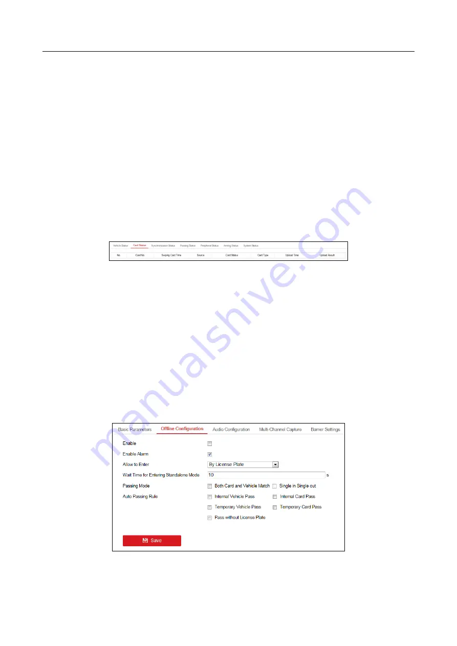
8.2 Configuring Offline Settings


Purpose 

When the station is disconnected with the platform, you can enable the offline mode to select the 
card mode, vehicle passing mode, automatic vehicle passing rule, etc. 

Step 1


Enter the Offline Configuration interface. 

Configuration > Entrance and Exit > Settings > Offline Configuration 


Figure 8-2


Offline Configuration 

Summary of Contents for DS-TME4 Series

Page 1: ...Entrance Exit Station User Manual UD03949B...

Page 2: ...ogos mentioned below are the properties of their respective owners Legal Disclaimer TO THE MAXIMUM EXTENT PERMITTED BY APPLICABLE LAW THE PRODUCT DESCRIBED WITH ITS HARDWARE SOFTWARE AND FIRMWARE IS P...

Page 3: ...interference 2 This device must accept any interference received including interference that may cause undesired operation EU Conformity Statement This product and if applicable the supplied accessor...

Page 4: ...ed repair or maintenance Preventive and Cautionary Tips Make sure the power supply voltage is correct before using the device Do not drop the device or subject it to physical shock Do not place the de...

Page 5: ...User Manual of DS TME4XX Series Entrance Exit Station 4 Improper use or replacement of the battery may result in hazard of explosion Please use the manufacturer recommended battery type...

Page 6: ...Data 19 5 1 Searching Card 19 5 2 Searching Vehicle 19 Chapter 6 Configuring General Parameters 21 6 1 Configuring Local Settings 21 6 2 Configuring System Settings 22 6 2 1 Configuring Basic Informa...

Page 7: ...Checking Synchronization Status 41 7 1 4 Checking Passing Status 42 7 1 5 Checking Peripheral Status 42 7 1 6 Checking Arming Status 42 7 1 7 Checking System Status 43 7 2 Configuring Entrance Exit S...

Page 8: ...hown in the following figure Table 1 1 Entrance Exit Station Model Functions DS TME401 TPL Entrance station supporting taking ticket LED display voice prompt etc DS TME402 TPL Exit station supporting...

Page 9: ...reak in Light on when the parking lot is full LED and voice prompt system Built in multiple RS 485 serial interfaces and 1 RJ45 network interface License plate number recognition to permit the vehicle...

Page 10: ...e indicator is on when the inductive loops detect the vehicle and off when the vehicle leaves the inductive loops completely 4 Parking Space Indicator The indicator is on when all the parking spaces a...

Page 11: ...ral devices Figure 2 1 Connection Interfaces Refer to the Figure 2 2 and Table 2 1 for the description of the interfaces Figure 2 2 Interfaces Description Table 2 1 Interfaces Description Pin Function...

Page 12: ...hernet Central Platform Entrance Exit Booth Figure 2 3 Device Connection You shall acknowledge that the use of the product with Internet access might be under network security risks For avoidance of a...

Page 13: ...0 for web browser activation and 37020 for SADP activation The default user account admin 3 1 1 Activating via SADP SADP software is enclosed in the disc You can also download it from the company webs...

Page 14: ...tivation and the device information will be displayed on the right side On Activate the Device interface create a password for the device and confirm the password The system will judge password streng...

Page 15: ...s activated hint window pops up when the password is set successfully Step 4 Modify the network parameters Select the device to be modified in the device list by checking the checkbox and the network...

Page 16: ...3 4 Activate via Web Browser Step 3 Enter a new password and click OK to activate the device The default IP address of the entrance exit station is 192 0 0 64 You are highly recommended to use a stro...

Page 17: ...before other operations Click Please click here to download and install the plug in Close the browser when installing the plug in on the live view page run and install the plug in according to the pr...

Page 18: ...the Live View interface see the following table for the functions of the interface icons Table 4 1 Icon Description Icon Name Description Start Stop Live View of the Selected Camera Start Stop live v...

Page 19: ...top recording of all the cameras Enable Disable e PTZ Enable Disable e PTZ function Prev Page Go for live view of the previous page Next Page Go for live view of the next page Audio On Off Turn on off...

Page 20: ...to enter the Card Search interface Figure 5 1 Card Search Step 2 Optional On the Search Condition panel select the Card Type All Internal Card and Temporary Card are selectable The default option is A...

Page 21: ...2 Vehicle Search Step 2 Optional Input the License Plate Number in the text field Step 3 Optional Select the Vehicle Type All Light Duty Vehicle Oversize Vehicle and Other are selectable Step 4 Optio...

Page 22: ...etwork is not stable Select MULTICAST when there are multiple users and you need to configure multicast address before you select it 2 Stream Type Main Stream and Sub Stream are selectable 3 Play Perf...

Page 23: ...ures in live view to Click Browse to set the local path to save the captures in live view 6 2 Configuring System Settings 6 2 1 Configuring Basic Information Step 1 Enter the Basic Information interfa...

Page 24: ...ime Zone Step 3 Configure the synchronization NTP Time Synchronization or Manual Time Synchronization NTP After enabling NTP the NTP server will synchronize the device time at regular intervals 1 Clic...

Page 25: ...DST Bias Step 5 Click Save to save the settings 6 2 3 Maintenance Step 1 Enter the Maintenance interface Configuration System Maintenance Upgrade Maintenance Figure 6 4 Maintenance Step 2 Configure t...

Page 26: ...the device Upgrade 1 Click Browse to select the upgrade file from the computer 2 Click Upgrade to upgrade the firmware The device will reboot automatically after upgrading Don t disconnect power to t...

Page 27: ...e the IP cameras Managing Analog Camera Step 1 Enter the Analog Camera management interface Configuration System Camera Management Analog Camera Figure 6 6 Analog Camera Step 2 View the information of...

Page 28: ...ess Management Port User Name and Password of the IP camera 3 Confirm the password 4 Click OK to add it and the added camera will be displayed on the IP Camera interface Quick Add 1 Click Quick Add to...

Page 29: ...sword of the IP camera 4 Click OK to save the settings Deleting the Added IP Camera 1 On the IP Camera interface check the checkbox of the camera for deleting 2 Click Delete to delete it 6 2 6 Managin...

Page 30: ...Entrance Exit Station 29 Figure 6 11 User Management Adding User Step 1 Click Add to enter the Add User interface Figure 6 12 Add User Step 2 Input the User Name select the Level as Operator or User i...

Page 31: ...password regularly especially in the high security system resetting the password monthly or weekly can better protect your product Step 3 Check the checkbox es to select the user permission s Step 4...

Page 32: ...count for deleting Step 2 Click Delete to delete it You cannot delete the admin account 6 3 Configuring Network Purpose You can configure TCP IP port and two way audio for the network configuration 6...

Page 33: ...Step 1 Enter the Port configuration interface Configuration Network Basic Settings Port Figure 6 15 Port Configuration Step 2 View the port parameters including HTTP Port 80 by default RTSP Port 554...

Page 34: ...ep 3 Click Save to save the settings 6 4 Configuring Image 6 4 1 Configuring Display Settings Step 1 Enter the Display Settings interface Configuration Image Display Settings Figure 6 17 Display Setti...

Page 35: ...6 Sharpness Slide the bar to adjust sharpness of the image It enhances the details of the image by sharpening the edges in the image The value ranges from 0 to 255 7 Denoising Slide the bar to adjust...

Page 36: ...n live view Step 4 Select the Display Mode from the drop down list Transparent Flashing Transparent Not Flashing Not Transparent Flashing Not Transparent Not Flashing are selectable Step 5 Optional Cl...

Page 37: ...w 3 Click Stop Drawing to finish drawing 4 Optional Click Clear All to clear all the configured privacy masks Step 5 Click Save to save the settings Privacy Mask function may not be supported by certa...

Page 38: ...ing Schedule and the Linkage Method Task 1 Configuring the Arming Schedule 1 Click Arming Schedule to edit the arming schedule Figure 6 21 Arming Schedule Setting 2 Drag the time bar to set the time p...

Page 39: ...he Linkage Method 1 Click Linkage Method to enter the Linkage Method interface 2 Configure the Normal Linkage Triggered Alarm Output Triggered Channel and PTZ Linking The linkage methods vary with dif...

Page 40: ...tput Figure 6 25 Alarm Output Step 2 Select the Alarm Output No from the drop down list Step 3 Optional Edit the Alarm Name Step 4 Select the Delay time 5 s 10 s 30 s 1 min 2 min 5 min 10 min and Manu...

Page 41: ...el the alarm Step 8 Click Save to save the settings Alarm output settings vary with different models 6 5 3 Configuring Exceptions Step 1 Enter the Exception interface Configuration Event Basic Event E...

Page 42: ...d Result 7 1 2 Checking Ticket Card Status Purpose For the Ticket Station you can view the ticket status For the Card Station you can view the card status Step 1 Enter the Ticket Card Status interface...

Page 43: ...he vehicle passing information including Mode Passing Result and Passing Time 7 1 5 Checking Peripheral Status Step 1 Enter the Peripheral Status interface Configuration Entrance and Exit Status Perip...

Page 44: ...p 1 Enter the Basic Parameters interface Configuration Entrance and Exit Settings Basic Parameters Figure 7 9 Basic Parameters Step 2 Configure the following parameters according to your needs Input t...

Page 45: ...udge whether the card information is legal or not Check the checkbox of Verify Key Before Writing Card The encrypted information of the internal card data will be verified and the card information wil...

Page 46: ...o save the settings 7 2 3 Configuring Audio Step 1 Enter the Audio Configuration interface Configuration Entrance and Exit Settings Audio Configuration Figure 7 11 Audio Configuration Step 2 Check the...

Page 47: ...d image with the highest confidence to upload Step 3 Input the Matching Time The value ranges from 0 to 1000 and 300 is recommended Step 4 Click Save to save the settings 7 2 5 Configuring Barrier Set...

Page 48: ...Configuration Step 2 Check the checkbox of Enable Log to enable the function Step 3 Configure the Log Module Log Level Export Log and Log Time Step 4 Click Browser under Export to select the director...

Page 49: ...cking Card Status Step 1 Enter the Card Status interface Configuration Entrance and Exit Status Card Status Figure 8 1 Card Status Step 2 Check the information including Card No Swiping Card Time Sour...

Page 50: ...line mode Step 3 Check the checkbox of Enable Alarm to enable alarm Step 4 Select the entering method Allow to enter by license plate or by card Step 5 Input the Wait Time for Entering Standalone Mode...

Page 51: ...User Manual of DS TME4XX Series Entrance Exit Station 50...

Reviews: