


Video Intercom Vandal-Resistant Door Station
·
Quick Start Guide
5
Name
No.
Interface
Description
B3
NC
Door Lock Relay Output
(Connect Electric Bolt or
Magnetic Lock)
3.2
Wiring Description
3.2.1
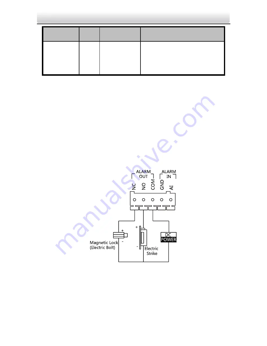
Door Lock Wiring
Terminal NC/COM is set as default for connecting magnetic
lock/electric bolt; terminal NO/ COM is set as default for connecting
electric strike.
To connect electric lock, it is required to set the output of terminal
NC/ COM/ NO to be electric lock via Batch Configuration Tool or
iVMS-4200 client software or the web browser.
Figure 3-2
Door Lock Wiring


