background image

DS-K1107A Series Card Reader • User Manual 


Chapter 3 Sound Prompt and Indicator 

After the card reader is powered on, LED status indicator will turn green and flashing for 1 time. 
Then it will turn red and flashing for 3 times. At last the buzzer will send out a beep sound 
indicating the starting up process is completed. 

When using the card reader, it will send out different sounds prompt and the LED indicator to 
indicate different statuses. You can refer to tables below for detailed information. 


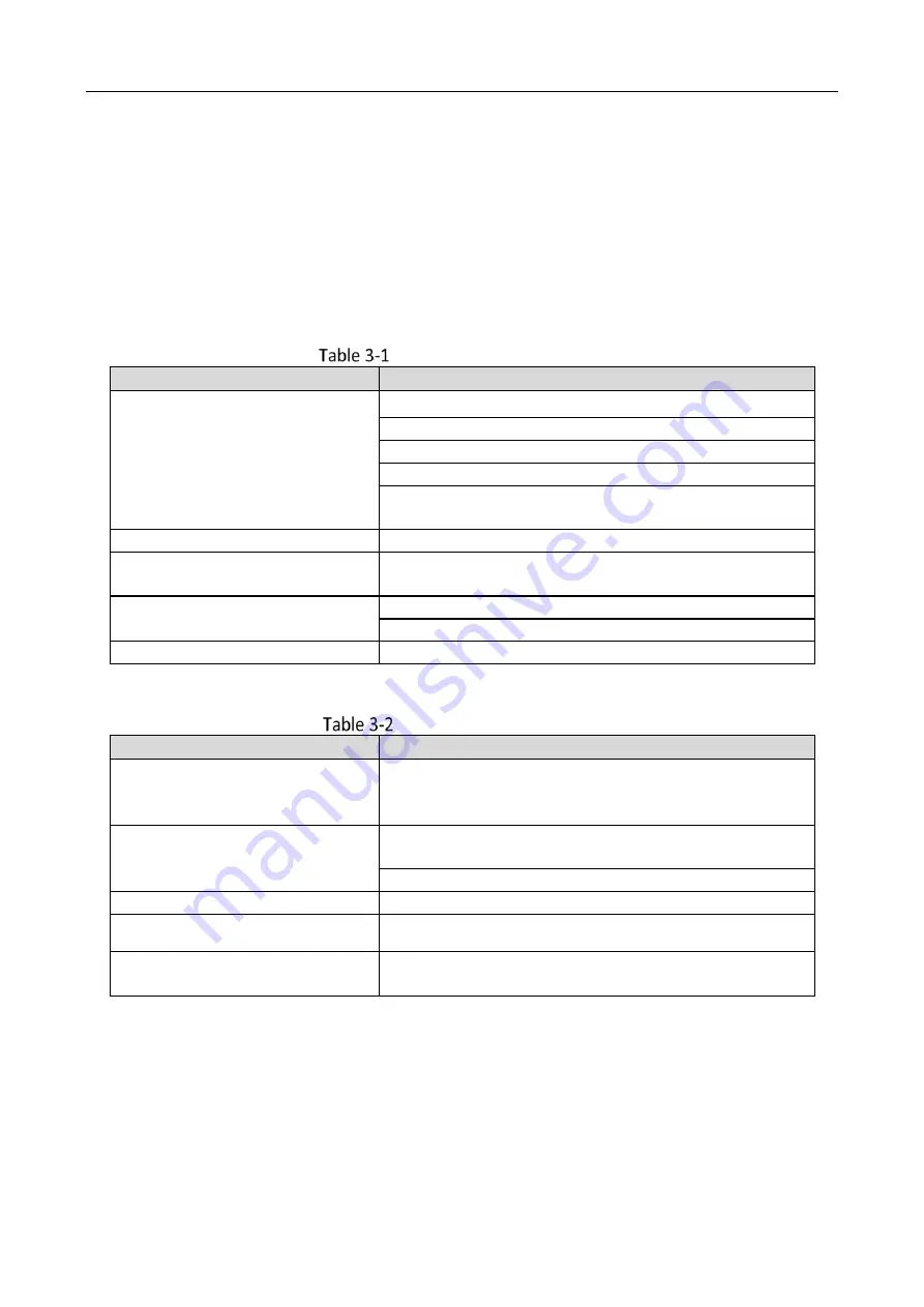
Description of Prompt Sound 

Sound Prompt 

Description 

One beep 

Swiping card prompt 

Pressing keys prompt 
Prompt for too long card No. input by pressing keys. 
Time out prompt for pressing keys or swiping card. 
For  Card  +  Fingerprint  authentication:  prompt  for 
pressing the fingerprint after swiping the card. 

Two rapid beeps 

The operation of pressing keys or swiping card is valid. 

Three slow beeps 

The  operation  of  pressing  keys  or  swiping  card  is 
invalid. 

Rapidly continuous beeps 

Prompt for tamper-proof alarm. 
Prompt for buzzer alarm.   

Slowly continuous beeps 

The card reader is unencrypted. 


Description of LED Indicator 

LED Indicator Status 

Description 

Green  (flashing  for  1  time),  and 
red (flashing for 3 times) 

The card reader is power on. 

Flashing green 

For Card + Password authentication: prompt for entering 
the password after swiping the card. 
The operation of configuring the fingerprint. 

Solid green for 2s 

The operation of pressing keys or swiping card is valid. 

Solid red 

Card reader is working normally. 

Flashing red for 3 times 

For RS-485 protocol: Registering failed or card reader is 
offline. 


Summary of Contents for DS-K1107A Series

Page 1: ...0 DS K1107A Series Card Reader User Manual...

Page 2: ...LITY OF SUCH DAMAGES OR LOSS YOU ACKNOWLEDGE THAT THE NATURE OF THE INTERNET PROVIDES FOR INHERENT SECURITY RISKS AND HIKVISION SHALL NOT TAKE ANY RESPONSIBILITIES FOR ABNORMAL OPERATION PRIVACY LEAKA...

Page 3: ...107A Series Card Reader User Manual II such as implementing reasonable administrative and physical security controls conduct periodic reviews and assessments of the effectiveness of your security cont...

Page 4: ...help The device must not be co located or operating in conjunction with any other antenna or transmitter This equipment should be installed and operated with a minimum distance 20cm between the radia...

Page 5: ...h this symbol which may include lettering to indicate cadmium Cd lead Pb or mercury Hg For proper recycling return the battery to your supplier or to a designated collection point For more information...

Page 6: ...re that the power has been disconnected before you wire install or dismantle the device When the product is installed on wall or ceiling the device shall be firmly fixed If smoke odors or noise rise f...

Page 7: ...ack them for future use In case of any failure occurred you need to return the device to the factory with the original wrapper Transportation without the original wrapper may result in damage on the d...

Page 8: ...V TABLE OF CONTENTS Chapter 1 Introduction 1 Overview 1 Indicator and Component 2 Chapter 2 Installation 3 Introduction for DIP Switch 3 Definition of Cable 4 Wiring Cables 5 Installing Card Reader 6...

Page 9: ...erformance product with a 32 bit high speed processor It communicates with access controller via either RS 485 protocol AES encrypted or Wiegand protocol And a build in tamper proof module helps to pr...

Page 10: ...DS K1107A Series Card Reader User Manual 2 Indicator and Component Indicator and Component...

Page 11: ...Switch The DIP switch module is shown below The No of DIP switch from left to right is 1 8 DIP Switch Module Description of DIP Switch Icon Description Represent 1 in binary mode Represent 0 in binar...

Page 12: ...nction disable door open via NFC card 0 Disable M1 card encryption function disable non M1 card Recognition function enable door open via NFC card 6 Wiegand protocol or RS 485 protocol 1 Wiegand proto...

Page 13: ...iegand Protocol Brown Green LED Control available for Wiegand Protocol Wiring Cables Purpose Wire the cables between controller and card reader thus to establish the communication between them Steps f...

Page 14: ...wn Controller Card Reader Card Reader Card Reader Green Wiring for Wiegand Communication Mode Installing Card Reader Before you start Set the DIP switch For details refer to 2 1 Introduction for DIP S...

Page 15: ...iping card For Card Fingerprint authentication prompt for pressing the fingerprint after swiping the card Two rapid beeps The operation of pressing keys or swiping card is valid Three slow beeps The o...

Page 16: ...0 UD25698B...

Reviews: