


Recognition Server Quick Start Guide
5
Chapter 1 Panel Description
1.1 Front Panel
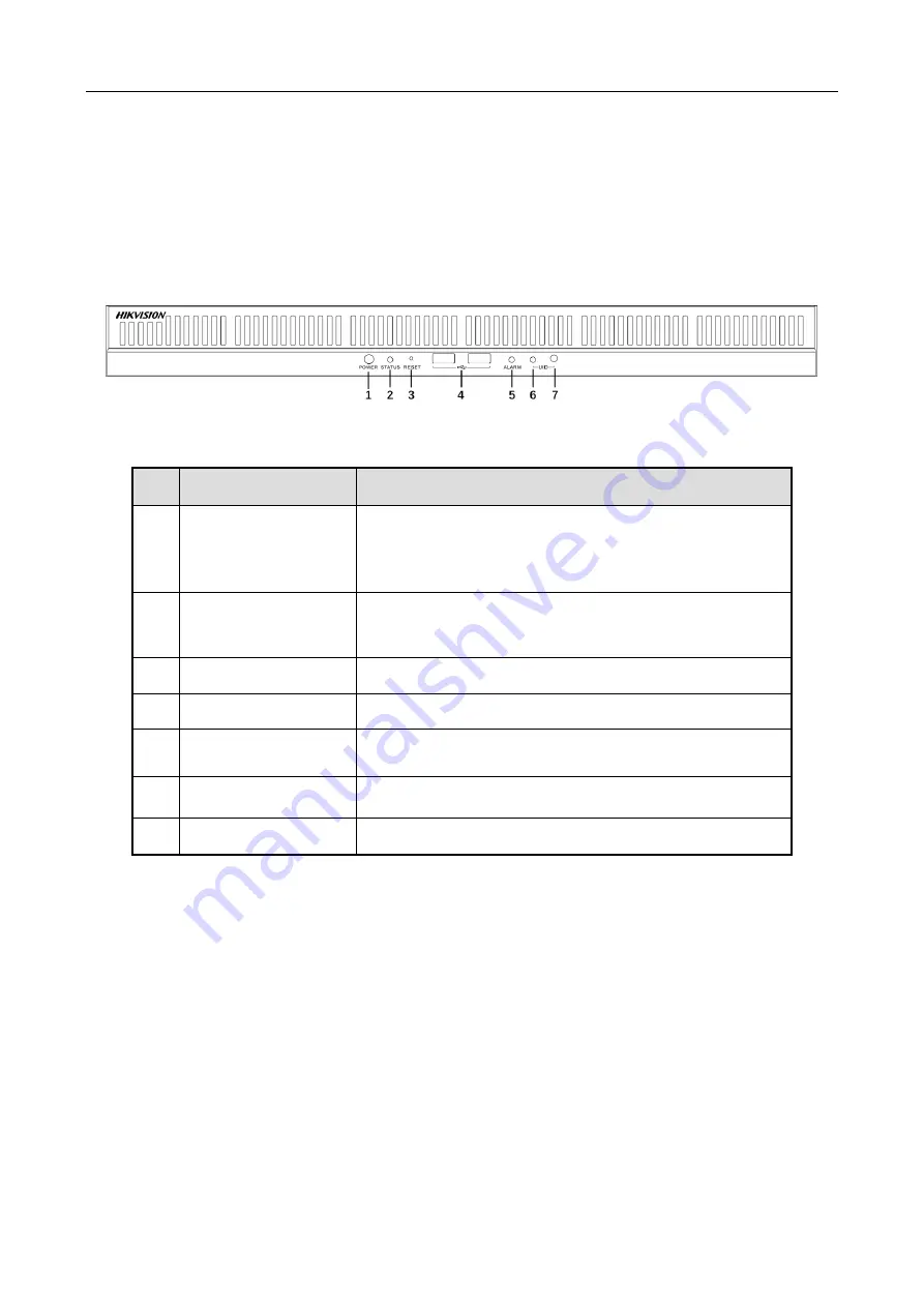
Figure 1-1
Front Panel
Table 1-1
Panel Description
No. Name
Function Description
1
Power button
Press it to power on device. The button is blue when
device is on.
Hold it for 3 seconds to force shut down the device.
2
Status indicator
Solid blue: System is naormal.
Unlit: System is abnormal.
3
Reset button
Press it to restore device to defaults.
4
USB interfaces
Two USB 2.0 interfaces for connecting USB devices.
5
Alarm indicator
Solid red when motherboard is abnormal.
6
UID indicator
Used to position server. It is blue when UID is on.
7
UID button
Turn on/off UID indicator.
Summary of Contents for DS-IE1024-03U/BA
Page 1: ...Recognition Server Quick Start Guide...
Page 12: ...UD13496B B...


