background image

Multi-Functional Card    User Manual 

iii 

Applicable Models 

This manual is applicable to the multi-functional card 2.0.


Symbol Conventions 

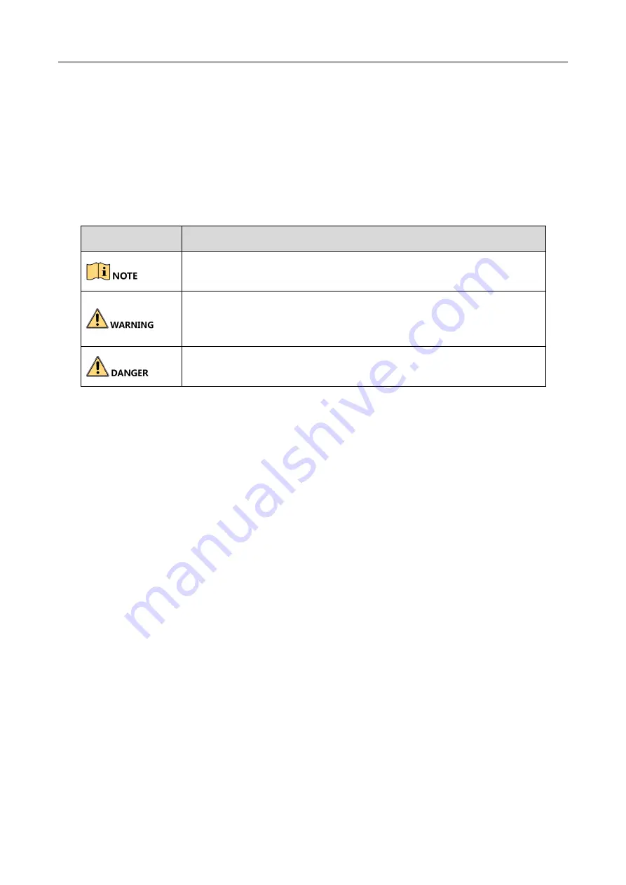
The symbols that may be found in this document are defined as follows. 


Symbol 

Description 


Provides  additional  information  to  emphasize  or  supplement 
important points of the main text. 


Indicates  a  potentially  hazardous  situation,  which  if  not  avoided, 
could  result  in  equipment  damage,  data  loss,  performance 
degradation, or unexpected results. 


Indicates a hazard with a high level of risk, which if not avoided, will 
result in death or serious injury. 

Summary of Contents for DS-D42AM2

Page 1: ...Multi Functional Card User Manual i Multi Functional Card User Manual ...

Page 2: ...rties of their respective owners Legal Disclaimer TO THE MAXIMUM EXTENT PERMITTED BY APPLICABLE LAW THE PRODUCT DESCRIBED WITH ITS HARDWARE SOFTWARE AND FIRMWARE IS PROVIDED AS IS WITH ALL FAULTS AND ERRORS AND HIKVISION MAKES NO WARRANTIES EXPRESS OR IMPLIED INCLUDING WITHOUT LIMITATION MERCHANTABILITY SATISFACTORY QUALITY FITNESS FOR A PARTICULAR PURPOSE AND NON INFRINGEMENT OF THIRD PARTY IN NO...

Page 3: ...ence 2 This device must accept any interference received including interference that may cause undesired operation EU Conformity Statement This product and if applicable the supplied accessories too are marked with CE and comply therefore with the applicable harmonized European standards listed under the EMC Directive 2014 30 EU the LVD Directive 2014 35 EU the RoHS Directive 2011 65 EU 2012 19 EU...

Page 4: ...efined as follows Symbol Description Provides additional information to emphasize or supplement important points of the main text Indicates a potentially hazardous situation which if not avoided could result in equipment damage data loss performance degradation or unexpected results Indicates a hazard with a high level of risk which if not avoided will result in death or serious injury ...

Page 5: ...d first to enable 3D function of the multifunctional card Refer to the user manual of LED display for details 1 2 Physical Interface 1 2 1 Front Panel The appearance and description of the front panel are shown as below Figure 1 1 Front Panel Table 1 1 Front Panel Description Name Description Name Description 12V GND Sensor interface RS232 Serial interface for remote telecommunication 3 3V GND SCL...

Page 6: ... Figure 1 2 Rear Panel Table 1 2 Rear Panel Description Name Description Name Description IR IN Infrared input interface requiring to connect with an IR extension cable DATA Interface for connecting with the receiving card IR OUT Infrared out interface WLAN Ethernet interface 3D OUT 3D interface DC IN 12V Power interface ...

Page 7: ...are recommended to connect it to the last receiving card as shown in the following figure Receiving Card WLAN WLAN Sending Card WLAN Receiving Card WLAN WLAN Receiving Card WLAN WLAN Receiving Card WLAN WLAN Multi Functional Card WLAN WLAN Figure 2 1 Hardware Connection If the multi functional card is connected directly to the sending card extra configuration on the client is needed Refer to the u...

Page 8: ...connect to half of the original devices to prevent screen flickering Prerequisites The multi functional card is connected correctly See Chapter 2 Hardware Connection for details Steps Step 1 Connect the 3D accessory such as glasses to 3D OUT on the multi functional card Step 2 Input signal source Step 3 Log in to the client Step 4 Select Screen Management Advanced Operation Input Capability Step 5...

Page 9: ...n file The remote control implements functions such as signal source switching brightness adjustment display on off detection scene switching etc The remote control is available within 10 m and 45o angle away from the multi functional card 3 3 Extended Functions The multi functional card has 5 extended interfaces to implement functions such as voltage detection temperature detection and smoke or l...

Page 10: ...nal Card User Manual 6 Appendix A Description of the Remote Control Power Signal Source Brightness Scene Volume Directional Button Return Menu Shortcut Help ID System Information 3D Dehumidification Auto Resolution ...

Page 11: ...ess and press Directional Button to increase decrease brightness Scene Switch scenes Directional Button Press Up Down Left Right to select menu items OK Confirm selection Return Back to the previous menu Menu Enter the main menu Shortcut Quickly access to System Information 3D Dehumidification and Auto Resolution Help Show the button descriptions of the remote control ID Select multi displays Numb...

Page 12: ...Multi Functional Card User Manual 8 UD15440B ...

Reviews: