HIKVISION DS-8104AHGHI-E4 Quick Start Manual Download Page 28

Digital Video Recorder Quick Start Guide   

27 


Figure 3. 23


Playback from Right-click Menu


2.


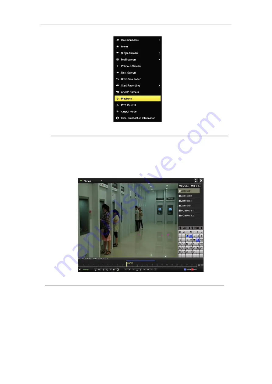
Playback management. 

The toolbar in the bottom part of Playback interface can be used to control playing process. 

The channel and time selection menu will display by moving the mouse to the right of the playback interface. 

Tick the channel or channels if you want to switch playback to another channel or execute simultaneous 

playback of multiple channels.   


Figure 3. 24


Playback Interface


3.13


Backup


Purpose: 

Recorded files can be backed up to various devices, such as USB flash drives, USB HDDs or a DVD writer. 

To export recorded files, follow the steps below. 

Steps: 

1.


Enter Video Export interface.   

Summary of Contents for DS-8104AHGHI-E4

Page 1: ...Digital Video Recorder Quick Start Guide UD04622B A ...

Page 2: ...2 Termination Switch Connection 13 2 4 HDD Storage Calculation Chart 14 Chapter 3Menu Operation 15 3 1 Menu Structure 15 3 2 Startup and Shutdown 15 3 3 Activating Your Device 16 3 4 Login and Logout 17 User Login 17 User Logout 18 3 5 Using the Setup Wizard 19 3 6 Network Settings 19 3 7 General Settings 20 3 8 Adding IP Cameras 21 3 9 Live View 23 3 10 ATM Settings 24 3 11 Recording Settings 25 ...

Page 3: ...rademarks and logos mentioned below are the properties of their respective owners Legal Disclaimer TO THE MAXIMUM EXTENT PERMITTED BY APPLICABLE LAW THE PRODUCT DESCRIBED WITH ITS HARDWARE SOFTWARE AND FIRMWARE IS PROVIDED AS IS WITH ALL FAULTS AND ERRORS AND HIKVISION MAKES NO WARRANTIES EXPRESS OR IMPLIED INCLUDING WITHOUT LIMITATION MERCHANTABILITY SATISFACTORY QUALITY FITNESS FOR A PARTICULAR ...

Page 4: ...ference 2 This device must accept any interference received including interference that may cause undesired operation EU Conformity Statement This product and if applicable the supplied accessories too are marked with CE and comply therefore with the applicable harmonized European standards listed under the EMC Directive 2014 30 EU the LVD Directive 2014 35 EU the RoHS Directive 2011 65 EU 2012 19...

Page 5: ...ase make sure that the plug is firmly connected to the power socket If smoke odor or noise rise from the device turn off the power at once and unplug the power cable and then please contact the service center Preventive and Cautionary Tips Before connecting and operating your device please be advised of the following tips Ensure unit is installed in a well ventilated dust free environment Unit is ...

Page 6: ...S 8104AHGHLI E4 Symbol Conventions The symbols that may be found in this document are defined as follows Symbol Description Indicates a potentially hazardous situation which if not avoided could result in equipment damage data loss performance degradation or unexpected results Provides additional information to emphasize or supplement important points of the main text ...

Page 7: ... Name Function Description 1 DIRECTION The DIRECTION buttons are used to navigate between different fields and items in menus In the Playback mode the Up and Down button is used to speed up and slow down recorded video The Left and Right button will select the next and previous record files In Live View mode these buttons can be used to cycle through channels In PTZ control mode it can control the...

Page 8: ...iver Receiver for IR remote control 5 POWER Power indicator Turn on off the device Power indicator stays red when the device is powered on but is not turned on Power indicator turns pink when the device is being turned on Power indicator stays blue when the device has been turned on 6 USB Interface Universal Serial Bus USB ports for additional devices such as USB mouse and USB Hard Disk Drive HDD ...

Page 9: ...r audio output 5 HDMI HDMI video output connector 6 VGA DB15 connector for VGA output Display local video output and menu 7 RS 232 Interface Connector for RS 232 devices 8 LAN Interface RJ45 10M 100M Ethernet interface 9 DC Output 12 VDC output 10 ALARM IN Connector for alarm input 11 RS 485 Interface Connector for RS 485 devices 12 ALARM OUT Connector for alarm output 13 GND Ground 14 Power Switc...

Page 10: ... grounded 7 Environmental temperature should be within the range of 10º C to 55º C 14º F to 131º F 8 Environmental humidity should be within the range of 10 to 90 2 2 Hard Disk Installation Before you start Before installing a hard disk drive HDD please make sure the power is disconnected from the DVR A factory recommended HDD should be used for this installation Four SATA hard disks can be instal...

Page 11: ...racket Figure 2 4 Tighten the Screw 6 Re install the cover of the DVR and fasten screws Figure 2 5 Re install the Cover 2 3 Peripheral Connections Wiring of Alarm Input The alarm input is an open closed relay To connect the alarm input to the device use the following diagram If the alarm input is not an open close relay please connect an external relay between the alarm input and the device ...

Page 12: ...d within the limit of 12V 1A safely To connect an AC load jumpers should be left open you must remove the jumper on the motherboard in the DVR Use an external relay for safety as shown in the figure above There are 4 jumpers JP1 JP2 JP3 and JP4 on the motherboard each corresponding with one alarm output By default jumpers are connected To connect an AC load jumpers should be removed Example If you...

Page 13: ...s and hold the orange part of the pluggable block insert signal cables into slots and release the orange part Ensure signal cables are in tight 3 Connect A on PTZ to T on terminal block and B on PTZ to T on terminal block Fasten stop screws 4 Connect pluggable block back into terminal block To connect a controller to the DVR 1 Disconnect pluggable block from the KB terminal block 2 Press and hold ...

Page 14: ... of 485 wire the longer the wire is the greater the impedance gets To avoid the signal reduction caused by the great impedance of long distance transmission connect two 120Ω resistors in the circuit one between the DVR and the nearest speed dome and the other one after the furthest speed dome which means turning on the SW switches on the DVR and the furthest speed dome Please make sure that the SW...

Page 15: ...e Bit Rate Storage Used 96K 42M 128K 56M 160K 70M 192K 84M 224K 98M 256K 112M 320K 140M 384K 168M 448K 196M 512K 225M 640K 281M 768K 337M 896K 393M 1024K 450M 1280K 562M 1536K 675M 1792K 787M 2048K 900M 4096K 1 8G 8192K 3 6G 16384K 7 2G Please note that supplied values for storage space used are just for reference Storage space used is estimated by formulas and may have some deviation from actual ...

Page 16: ... PTZ Upgrade Motion Live View Default Privacy Mask Exceptions Net Detect Video Tampering User Video Loss HDD Detect Alarm Normal ATM Event Tag Sub periods External File Continuous Capture Alarm Video Quality Diagnostics ATM RS 232 Picture Picture Manual Video Quality Diagnostics Figure 3 1 Menu Structure 3 2 Startup and Shutdown Proper startup and shutdown procedures are crucial to expanding the l...

Page 17: ...ins to start up Shutting down the device Steps 1 Enter the Shutdown menu Menu Shutdown Figure 3 2 Shutdown 2 Click the Shutdown button 3 Click the Yes button 4 Disconnect the power supply of the device 3 3 Activating Your Device Purpose For the first time access you need to activate the device by setting an admin password No operation is allowed before activation You can also activate the device v...

Page 18: ...system resetting the password monthly or weekly can better protect your product 2 Click OK to save the password and activate the device For the old version device if you upgrade it to the new version the following dialog box will pop up once the device starts up You can click YES and follow the wizard to set a strong password Figure 3 4 Warning of Weak Password 3 4 Login and Logout User Login Purp...

Page 19: ...ng password for 5 times the account will be locked for 60 seconds Figure 3 6 User Account Protection for the Admin Figure 3 7 User Account Protection for the Operator User Logout Purpose After logging out the monitor turns to the live view mode and if you want to perform any operations you need to enter user name and password log in again Steps 1 Enter the Shutdown menu Menu Shutdown Figure 3 8 Lo...

Page 20: ...izard starts once the device is activated Check the checkbox to enable Setup Wizard when device starts Click Next to continue the setup wizard Follow the guide of the Setup Wizard to configure the system language system date time network settings HDD management record settings etc Figure 3 9 Wizard 3 6 Network Settings Purpose Network settings must be properly configured before you operate DVR ove...

Page 21: ... General Settings interface Menu Configuration General 2 Select the General tab Figure 3 11 General Settings Interface 3 Configure the following settings Language The default language used is English VGA HDMI Resolution Select the output resolution which must be the same with the resolution of the VGA HDMI display The LCD HDMI and VGA share simultaneous output If the external display is not connec...

Page 22: ... Time Zone Select the time zone Date Format Select the date format System Date Select the system date System Time Select the system time Mouse Pointer Speed Set the speed of mouse pointer 4 levels are configurable Enable Wizard Enable disable the Wizard when the device starts up Enable Password Enable disable the use of the login password 4 Click the Apply button to save the settings 3 8 Adding IP...

Page 23: ...and click the button to add the camera with the same admin password of the DVR s OPTION 2 Steps 1 Click the Custom Adding button to pop up the Add IP Camera Custom interface Figure 3 15 Add IP Camera 2 Select the detected IP camera and click the Add button to add it directly and you can click the Search button to refresh the online IP camera manually OPTION 3 You can choose to custom add the IP ca...

Page 24: ...ollowing menu Figure 3 16 Menu Table 3 1 Mouse Operation in Live View Name Description Menu Enter the main menu of the system by right clicking the mouse Single Screen Switch to the single full screen by choosing channel number from the dropdown list Multi screen Adjust the screen layout by choosing from the dropdown list Previous Screen Switch to the previous screen Next Screen Switch to the next...

Page 25: ...Select the input mode to Network Interception Serial Port Interception Network Protocol or Serial Port Protocol which refers to the connection type of the ATM DVR 4 Click the Setting button to enter the settings interface of the input mode you select The following steps give the settings of Serial Port Interception as the example Figure 3 18 Serial Port Interception 5 Select the protocol for the i...

Page 26: ...nual for detailed information Purpose You can use the right click menu in live view mode to configure recording for all channels Steps 1 In the live view mode use the mouse to right click on the window to access the following menu Figure 3 20 Start Recording from Right click Menu 2 Click the Start Recording submenu and select the recording mode to Continuous Record or Motion Detection Record 3 In ...

Page 27: ...playback by channel Choose a channel under live view using the mouse and click the button in the shortcut operation menu Only record files recorded during the past five minutes on this channel will be played back Figure 3 22 Instant Playback All day playback by channel 1 Enter the All day Playback menu Right click a channel in live view mode and select Playback from the menu Under multi screen liv...

Page 28: ...ill display by moving the mouse to the right of the playback interface Tick the channel or channels if you want to switch playback to another channel or execute simultaneous playback of multiple channels Figure 3 24 Playback Interface 3 13 Backup Purpose Recorded files can be backed up to various devices such as USB flash drives USB HDDs or a DVD writer To export recorded files follow the steps be...

Page 29: ...d click Search button to enter the search result interface You can also choose the channel s you want to back up and click the Quick Export button to enter the export interface Figure 3 26 Search Result 3 Select record files you want to back up 4 Enter Export interface choose backup device and click Export button to start exporting ...

Page 30: ...Digital Video Recorder Quick Start Guide 29 Figure 3 27 Export Interface ...

Page 31: ...resolutions include 1024 768 and above Steps 1 Open web browser input the IP address of the device and then press Enter 2 Login to the device If the device has not been activated you need to activate the device first before login Figure 4 1 Activation 1 Set the password for the admin user account 2 Click OK to login to the device STRONG PASSWORD RECOMMENDED We highly recommend you create a strong ...

Page 32: ... video and managing the camera Please follow the installation prompts to install the plug in You may have to close the web browser to finish the installation of the plug in After login you can perform the operation and configuration of the device including the live view playback log search configuration etc ...

Page 33: ...tput HDMI VGA output 1 ch 1920 1080 60Hz 1280 1024 60Hz 1024 768 60Hz Encoding resolution Main stream 720p WD1 VGA 4CIF 2CIF CIF 25fps P 30fps N Sub stream WD1 4CIF 12fps 2CIF CIF QCIF QVGA 25fps P 30fps N Frame rate 25fps P 30fps N Video bit rate 32 Kbps to 6 Mbps 3072 Kbps Audio output 1 ch BNC Linear 600 Ω Audio bit rate 64 Kbps Dual stream Support Stream type Video Video Audio Synchronous play...

Page 34: ...Recorder Quick Start Guide 33 0304021070209 Working temperature 10 º C to 55 º C 14 º F to 131 º F Working humidity 10 to 90 Dimensions W D H 180 280 180 mm 7 1 11 0 7 1 inch Weight without HDD or DVD R W 5 kg 11 lb ...

Page 35: ...Digital Video Recorder Quick Start Guide 34 ...

Reviews: