HIKVISION DS-7032NI-Q4 User Manual Download Page 140

Network Video Recorder User Manual   

139 

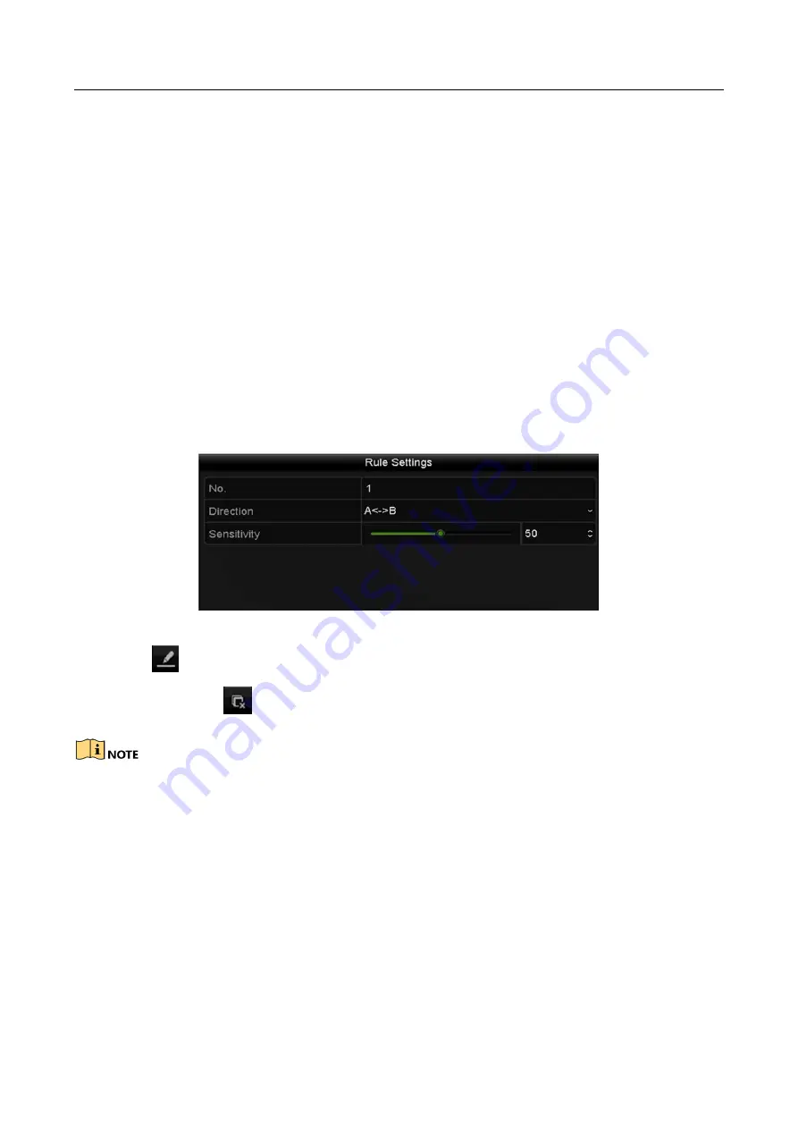
A<->B: Only the arrow on the B side shows; when an object going across the configured 

line with both direction can be detected and alarms are triggered.   

A->B: Only the object crossing the configured line from the A side to the B side can be 

detected.   

B->A: Only the object crossing the configured line from the B side to the A side can be 

detected. 

2)


Click-and-drag the slider to set the detection sensitivity. 

Sensitivity: Range [1-100]. The higher the value is, the more easily the detection alarm 
can be triggered. 

3)


Click-OK to save the rule settings and back to the line crossing detection settings 

interface. 


Figure 9-3


Set Line Crossing Detection Rules 

Step 7


Click 

  and set two points in the preview window to draw a virtual line.   

You can use the 

  to clear the existing virtual line and re-draw it.   


Up to 4 rules can be configured.   

Summary of Contents for DS-7032NI-Q4

Page 1: ...Network Video Recorder User Manual ...

Page 2: ...on Multimedia Interface and the HDMI Logo are trademarks or registered trademarks of HDMI Licensing Administrator Inc in the United States and other countries Legal Disclaimer TO THE MAXIMUM EXTENT PERMITTED BY APPLICABLE LAW THE PRODUCT DESCRIBED WITH ITS HARDWARE SOFTWARE AND FIRMWARE IS PROVIDED AS IS WITH ALL FAULTS AND ERRORS AND HIKVISION MAKES NO WARRANTIES EXPRESS OR IMPLIED INCLUDING WITH...

Page 3: ...ence 2 This device must accept any interference received including interference that may cause undesired operation EU Conformity Statement This product and if applicable the supplied accessories too are marked with CE and comply therefore with the applicable harmonized European standards listed under the EMC Directive 2014 30 EU the LVD Directive 2014 35 EU the RoHS Directive 2011 65 EU 2012 19 EU...

Page 4: ... DS 7608NI Q2 DS 7616NI Q2 DS 7600NI Q1 P DS 7604NI Q1 4P DS 7608NI Q1 8P DS 7600NI Q2 P DS 7608NI Q2 8P DS 7616NI Q2 16P DS 7600NI K1 B DS 7604NI K1 B DS 7608NI K1 B DS 7616NI K1 B DS 7600NI K1 P B DS 7604NI K1 4P B DS 7608NI K1 8P B DS 7700NI Q4 DS 7708NI Q4 DS 7716NI Q4 DS 7732NI Q4 DS 7700NI Q4 P DS 7708NI Q4 8P DS 7716NI Q4 16P DS 7732NI Q4 16P DS 8600NI Q8 DS 8608NI Q8 DS 8616NI Q8 DS 8632NI...

Page 5: ... connected to the power socket If smoke odor or noise rise from the device turn off the power at once and unplug the power cable and then please contact the service center Preventive and Cautionary Tips Before connecting and operating your device please be advised of the following tips Ensure unit is installed in a well ventilated dust free environment Unit is designed for indoor use only Keep all...

Page 6: ...ice Improper use or replacement of the battery may result in hazard of explosion Replace with the same or equivalent type only Dispose of used batteries according to the instructions provided by the battery manufacturer When installing the device into a cabinet over 2U height it is suggested to use rack shelf to bear the weight If the cabinet height is over 4U it is suggested to use slide rails or...

Page 7: ...l Monitoring HDMI and VGA outputs provided HDMI video output at up to 4K resolution Multiple screen display in live view is supported and the display sequence of channels is adjustable Live view screen can be switched in group Manual switch and auto switch are provided and the auto switch interval is configurable Configurable main stream and sub stream for the live view Quick setting menu is provi...

Page 8: ...rd files by channel number recording type start time end time etc Smart search for the selected area in the video Zooming in when playback Reverse playback of multi channel Supports pause play reverse speed up speed down skip forward and skip backward when playback and locating by dragging the mouse Supports thumbnails view and fast view during playback Up to 16 ch synchronous playback at 1080p re...

Page 9: ...dependent PoE network interfaces for the 16P models Long distance 100 300 m network transmission via PoE for P models IPv6 is supported TCP IP protocol DHCP DNS DDNS NTP SADP SMTP NFS and iSCSI are supported TCP UDP and RTP for unicast Auto Manual port mapping by UPnPTM Support access by Hik Connect Remote web browser access by HTTPS ensures high security The ANR Automatic Network Replenishment fu...

Page 10: ...t stop alarm output Remote PTZ control Remote JPEG capture Virtual host function is provided to get access and manage the IP camera directly Two way audio and voice broadcasting Embedded WEB server Development Scalability SDK for Windows system Source code of application software for demo Development support and training for application system ...

Page 11: ...vice Startup and Activation 29 2 1 1 Starting Up and Shutting Down the NVR 29 2 1 2 Activating Your Device 30 2 1 3 Using the Unlock Pattern for Login 31 2 1 4 Login and Logout 34 2 2 Using Wizard for Basic Configuration 35 2 3 Adding and Connecting the IP Cameras 39 2 3 1 Activating the IP Camera 39 2 3 2 Adding the Online IP Cameras 40 2 3 3 Editing the Connected IP Cameras and Configuring Custo...

Page 12: ...ng Linear Scan 70 4 2 9 One touch Park 71 4 3 PTZ Control Panel 73 Chapter 5 Recording Settings 75 5 1 Configuring Parameters 75 5 2 Configuring Recording Schedule 79 5 3 Configuring Motion Detection Recording 83 5 4 Configuring Alarm Triggered Recording 85 5 5 Configuring VCA Event Recording 87 5 6 Manual Recording 89 5 7 Configuring Holiday Recording 90 5 8 Configuring Redundant Recording 92 5 9...

Page 13: ...Event Search 119 7 1 4 Backing up Video Clips 120 7 2 Managing Backup Devices 121 Chapter 8 Alarm Settings 122 8 1 Setting Motion Detection Alarm 122 8 2 Setting Sensor Alarms 124 8 3 Detecting Video Loss Alarm 127 8 4 Detecting Video Tampering Alarm 129 8 5 Handling Exceptions Alarm 131 8 6 Setting Alarm Response Actions 132 8 7 Triggering or Clearing Alarm Output Manually 136 Chapter 9 VCA Alarm...

Page 14: ... HTTPS Port 160 11 2 8 Configuring Email 162 11 2 9 Configuring NAT 164 11 2 10 Configuring Virtual Host 167 11 3 Checking Network Traffic 167 11 4 Configuring Network Detection 169 11 4 1 Testing Network Delay and Packet Loss 169 11 4 2 Exporting Network Packet 169 11 4 3 Checking the Network Status 170 11 4 4 Checking Network Statistics 171 Chapter 12 HDD Management 173 12 1 Initializing HDDs 17...

Page 15: ... 14 5 1 Upgrading by Local Backup Device 198 14 5 2 Upgrading by FTP 199 14 6 Restoring Default Settings 200 Chapter 15 Others 201 15 1 Configuring General Settings 201 15 2 Configuring DST Settings 203 15 3 Configuring More Settings 204 15 4 Managing User Accounts 205 15 4 1 Adding a User 205 15 4 2 Deleting a User 208 15 4 3 Editing a User 208 15 5 Configure Password Security 211 15 5 1 Export G...

Page 16: ...atus Indicator Power Power indicator turns green when system is running Status Status indicator blinks red when data is being read from or written to HDD Tx Rx Tx Rx indictor blinks green when network connection is functioning properly 2 USB Interface Universal Serial Bus USB ports for additional devices such as USB mouse and USB Hard Disk Drive HDD DS 7600NI Q2 P Series Figure 1 2 DS 7600NI Q2 an...

Page 17: ...ata is being read from or written to HDD 3 Tx Rx Flickers blue when network connection is functioning properly 4 USB Interface Universal Serial Bus USB port for additional devices such as USB mouse and USB Hard Disk Drive HDD No Name Connections 1 POWER Turns white when device is powered up 2 HDD Flickers white when data is being read from or written to HDD 3 Tx Rx Flickers white when network conn...

Page 18: ... NVR by changing the Device ID as follows Pairing Enabling the IR Remote to a Specific NVR optional You can pair an IR Remote to a NVR by creating a user defined Device ID This feature is useful when using multiple IR Remotes and NVRs On the NVR Step 1 Go to General More Settings Step 2 Type a number 255 digits maximum into the Device No field Step 3 On the IR Remote Step 4 Press the DEV button St...

Page 19: ...ntrol any NVR functions proceed as follows Press the DEV key on the IR Remote Any existing Device ID will be erased from the unit s memory and it will no longer function with the NVR Re enabling the IR Remote requires pairing to a NVR See Pairing the IR Remote to a Specific NVR optional above The keys on the remote control closely resemble the ones on the front panel ...

Page 20: ...hlight desired selection 3 Press Enter button 12 to accept selection If User Is Not Logged On 1 Hold Power On Off button 1 down for five seconds to display the user name password prompt 2 Press the Enter button 12 to display the on screen keyboard 3 Input the user name 4 Press the Enter button 12 to accept input and dismiss the on screen keyboard 5 Use the Down Arrow button 12 to move to the Passw...

Page 21: ... 5 A Adjust focus in the PTZ Control menu Switch on screen keyboards upper and lower case alphabet symbols and numerals 6 REC Enter Manual Record setting menu Call a PTZ preset by using the numeric buttons in PTZ control settings Turn audio on off in Playback mode 7 PLAY Go to Playback mode Auto scan in the PTZ Control menu 8 INFO Reserved 9 VOIP Switches between main and spot output Zooms out the...

Page 22: ...zoom 18 F2 Cycle through tab pages Switch between channels in Synchronous Playback mode Troubleshooting Remote Control Make sure you have installed batteries properly in the remote control And you have to aim the remote control at the IR receiver in the front panel If there is no response after you press any button on the remote follow the procedure below to troubleshoot Step 1 Go to Menu Settings...

Page 23: ...nd there is still no response from the remote please check the following Batteries are installed correctly and the polarities of the batteries are not reversed Batteries are fresh and not out of charge IR receiver is not obstructed No fluorescent lamp is used nearby If the remote still can t function properly please change a remote and try again or contact the device provider ...

Page 24: ... provider The operation of the mouse Table 1 5 Description of the Mouse Control Name Action Description Left Click Single Click Live view Select channel and show the quick set menu Menu Select and enter Double Click Live view Switch between single screen and multi screen Click and Drag PTZ control pan tilt and zoom Video tampering privacy mask and motion detection Select target area Digital zoom i...

Page 25: ...board 1 Figure 1 6 Soft Keyboard 2 Description of the buttons on the soft keyboard Table 1 6 Description of the Soft Keyboard Icons Icon Description Icon Description Number English letter Lowercase Uppercase Backspace Switch the keyboard Space Positioning the cursor Exit Symbols Reserved ...

Page 26: ... Supply 12 VDC power supply 2 Audio In RCA connector for audio input 3 HDMI Interface HDMI video output connector 4 LAN Network Interface 1 10 100 1000 Mbps self adaptive Ethernet interface 5 Audio Out RCA connector for audio output 6 VGA Interface DB9 connector for VGA output Display local video output and menu 7 USB Interface Universal Serial Bus USB ports for additional devices such as USB mous...

Page 27: ...etwork Interface 1 10 100 1000 Mbps self adaptive Ethernet interface 5 Audio Out RCA connector for audio output 6 VGA Interface DB9 connector for VGA output Display local video output and menu 7 USB Interface Universal Serial Bus USB ports for additional devices such as USB mouse and USB Hard Disk Drive HDD 8 Ground Ground needs to be connected when NVR starts up 9 Power Switch Switch for turning ...

Page 28: ...io Out RCA connector for audio output 3 HDMI Interface HDMI video output connector 4 USB Interface Universal Serial Bus USB ports for additional devices such as USB mouse and USB Hard Disk Drive HDD 5 VGA Interface DB9 connector for VGA output Display local video output and menu 6 RS 485 Interface Half duplex connector for RS 485 devices 7 ALARM IN Connector for alarm input 8 Ground Ground needs t...

Page 29: ...2 Interface Connector for RS 232 devices 13 Audio In RCA connector for audio input 14 ALARM OUT Connector for alarm output optional 15 eSATA Connects external SATA HDD CD DVD RM 16 Network Interfaces with PoE function Network interfaces for the cameras and to provide power over Ethernet ...

Page 30: ...y UPS be used in conjunction with the device The Power indicator LED on the front panel should be red indicating the device gets the power supply Step 2 Press the POWER button on the front panel The Power indicator LED should turn blue indicating that the unit begins to start up Step 3 After startup the Power indicator LED remains blue A splash screen with the status of the HDD appears on the moni...

Page 31: ...g down Rebooting the NVR In the Shutdown menu you can also reboot the NVR Step 1 Enter the Shutdown menu by clicking Menu Shutdown Step 2 Click the Logout button to lock the NVR or the Reboot button to reboot the NVR 2 1 2 Activating Your Device Purpose For the first time access you need to activate the device by setting an admin password No operation is allowed before activation You can also acti...

Page 32: ...the IP camera s connected to the device Step 3 Optional Check Reserved E mail for future password resetting Step 4 Click OK What to do next Continue to export the GUID file to the USB flash driver for the future password resetting When you have enabled Reserved E mail continue to set the reserved email for the future password resetting 2 1 3 Using the Unlock Pattern for Login For the Admin user yo...

Page 33: ...st 4 dots to draw the pattern Each dot can be connected for once only Step 3 Draw the same pattern again to confirm it When the two patterns match the pattern is configured successfully Figure 2 5 Confirm the Pattern If the two patterns are different you must set the pattern again ...

Page 34: ... to unlock the device Please configure the pattern first before unlocking Please refer to Configuring the Unlock Pattern Step 1 Right click the mouse on the screen and select the menu to enter the interface as shown in Figure 2 8 Figure 2 7 Draw the Unlock Pattern Step 2 Draw the pre defined pattern to unlock to enter the menu operation ...

Page 35: ...n 5 times the system will switch to the normal login mode automatically Figure 2 8 Normal Login Dialog Box 2 1 4 Login and Logout User Login Purpose If NVR has logged out you must login the device before operating the menu and other functions Step 1 Select the User Name in the dropdown list Figure 2 9 Login Interface Step 2 Input password Step 3 Click OK to log in When you forget the password of t...

Page 36: ...rm any operations you need to enter user name and password log in again Step 1 Enter the Shutdown menu Menu Shutdown Figure 2 10 Logout Step 2 Click Logout After you have logged out the system menu operation on the screen is invalid It is required to input a user name and password to unlock the system 2 2 Using Wizard for Basic Configuration By default the Setup Wizard starts once the NVR has load...

Page 37: ...gure 2 12 Figure 2 12 Date and Time Settings Step 3 After the time settings click Next button which takes you back to the Network Setup Wizard window as shown in the following figure Figure 2 13 Network Settings Step 4 Click Next button after you configured the basic network parameters Enter the Hik Connect interface to configure the parameters Please refer to Chapter 11 2 1 Configuring Hik Connec...

Page 38: ...saved in the HDD Step 9 Click Next button You enter the Adding IP Camera interface Step 10 Click Search to search the online IP Camera and the Security status shows whether it is active or inactive Before adding the camera make sure the IP camera to be added is in active status If the camera is in inactive status you can click the inactive icon of the camera to set the password to activate it You ...

Page 39: ...ox of Enable H 265 the NVR can automatically switch to the H 265 stream of IP camera which supports H 265 video format for the initial access Step 11 Click Next button Configure the recording for the added IP Cameras Figure 2 17 Record Settings Step 12 Click OK to complete the startup Setup Wizard ...

Page 40: ...interface For the IP camera detected online in the same network segment the Password status shows whether it is active or inactive Figure 2 18 IP Camera Management Interface Step 2 Click the inactive icon of the camera to enter the following interface to activate it You can also select multiple cameras from the list and click the One touch Activate to activate the cameras in batch Step 3 Set the p...

Page 41: ...ity system resetting the password monthly or weekly can better protect your product Step 4 Click OK to finish the acitavting of the IP camera And the security status of camera will be changed to Active 2 3 2 Adding the Online IP Cameras Purpose The main function of the NVR is to connect the network cameras and record the video got from it So before you can get a live view or record of the video yo...

Page 42: ... directly and you can click the Search button to refresh the online IP camera manually Figure 2 21 Quick Adding IP Camera Interface Or you can choose to custom add the IP camera by editing the parameters in the corresponding textfiled and then click the Add button to add it OPTION 2 Step 1 Select the Add IP Camera option from the right click menu in live view mode or click Menu Camera Camera to en...

Page 43: ...st and click the button to add the camera Or you can click the One touch Adding button to add all cameras with the same login password from the list Make sure the camera to add has already been activated Step 4 For the encoders with multiple channels only check the Channel Port checkbox in the pop up window as shown in the following figure and click OK to add multiple channels Figure 2 23 Selectin...

Page 44: ...ddress protocol management port and other information of the IP camera to be added If the IP camera to add has not been actiavated you can activate it from the IP camera list on the camera management interface Step 3 Optional Check the checkbox of Continue to Add to add other IP cameras Step 4 Click Add to add the camera The successfully added cameras are listed in the interface Refer to the follo...

Page 45: ...ra Security Show the security status of the camera to be active inactive or the password strength strong medium weak risk For the added IP cameras the Security status shows the security level of the password of camera strong password weak password and risk password Figure 2 25 Security Level of IP Camera s Password Enabling the Password of IP Camera Visible For the admin login user account you can...

Page 46: ...stream of IP camera which supports H 265 video format for the initial access 2 3 3 Editing the Connected IP Cameras and Configuring Customized Protocols After the adding of the IP cameras the basic information of the camera lists in the page you can configure the basic setting of the IP cameras Step 1 Click the icon to edit the parameters you can edit the IP address protocol and other parameters ...

Page 47: ...he channel to connect by selecting the channel port No in the dropdown list Step 2 Click OK to save the settings and exit the editing interface To edit advanced parameters Step 1 Drag the horizontal scroll bar to the right side and click the icon Figure 2 28 Network Configuration of the Camera Step 2 You can edit the network information and the password of the camera ...

Page 48: ...ith the standard protocols you can configure the customized protocols for them Step 1 Click the Protocol button in the custom adding IP camera interface to enter the protocol management interface Figure 2 30 Protocol Management Interface There are 16 customized protocols provided in the system you can edit the protocol name and choose whether to enable the sub stream Step 2 Choose the protocol typ...

Page 49: ...e sub stream is not needed leave the checkbox empty Type The network camera adopting custom protocol must support getting stream through standard RTSP Transfer Protocol Select the transfer protocol for the custom protocol Port Set the port No for the custom protocol Path Set the resource path for the custom protocol E g ch1 main av_stream The protocol type and the transfer protocols must be suppor...

Page 50: ... Cameras Step 1 Connect PoE cameras to device PoE interfaces with network cables Step 2 Go to Camera Camera IP Camera to view camera image and information 2 4 2 Add Non PoE IP Cameras Purpose You can manually disable PoE function After PoE function is disabled the PoE channel becomes a normal channel and online network camera can be added Step 1 Go to Camera Camera IP Camera Step 2 You can add non...

Page 51: ... 2 32 Edit PoE Channel Parameter 4 Click OK Configure PoE channel as normal channel 1 Click Resource Management for PoE Channel 2 Disable the PoE channel s as your desire Disabling PoE channel will increase the channel for adding online IP camera ...

Page 52: ...onfigure PoE Interface When it requires long distance PoE transmission 100 to 300 m you can configure the PoE channel to the long network cable mode Step 1 Go to Menu Camera Camera PoE Settings Step 2 Switch on and off each PoE channel as your desire ON Long distance 100 300 meters network transmissions via POE interface OFF Short distance 100 meters network transmission via POE interface ...

Page 53: ...IP camera models and cable materials When the transmission distance reaches 100 to 250 meters you must use the CAT5E or CAT6 network cable to connect with the PoE interface When the transmission distance reaches 250 to 300 meters you must use the CAT6 network cable to connect with the PoE interface You can check the connecting status and power information of PoE channel on the interface Step 3 Cli...

Page 54: ... upper right of the screen for each channel showing the status of the record and alarm in the channel so that you can know whether the channel is recorded or whether there are alarms occur as soon as possible Table 3 1 Description of Live View Icons Icons Description Alarm video loss video tampering motion detection VCA and sensor alarm Record manual record schedule record motion detection VCA and...

Page 55: ...ng continuous record and motion detection record are supported Output Mode select the output mode to Standard Bright Gentle or Vivid Add IP Camera the shortcut to the IP camera management interface Playback playback the recorded videos for current day Aux Monitor the NVR checks the connection of the output interfaces to define the main and auxiliary output interfaces The priority level for the mai...

Page 56: ... 3 Mouse Operation in Live View Name Description Common Menu Quick access to the sub menus which you frequently visit Menu Enter the main menu of the system by right clicking the mouse Single Screen Switch to the single full screen by choosing channel number from the dropdown list Multi screen Adjust the screen layout by choosing from the dropdown list Previous Screen Switch to the previous screen...

Page 57: ...e If the corresponding camera supports intelligent function the Reboot Intelligence option is included when right clicking mouse on this camera Figure 3 1 Right click Menu 3 2 3 Using an Auxiliary Monitor Certain features of the Live View are also available while in an Aux monitor These features include Single Screen Switch to a full screen display of the selected camera Camera can be selected fro...

Page 58: ...r Table 3 4 Description of Quick Setting Toolbar Icons Icon Description Icon Description Icon Description Enable Disable Manual Record Instant Playback Mute Audio on Capture PTZ Control Digital Zoom Image Settings Live View Strategy Information Main Sub Stre am Close Instant Playback only shows the record in last five minutes If no record is found it means there is no record during the last five m...

Page 59: ...ed to enter the Image Settings menu You can set the image parameters like brightness contrast saturation and hue according to the actual demand Figure 3 4 Image Settings Customize Live View Strategy can be selected to set strategy including Real time Balanced Fluency Figure 3 5 Live View Strategy ...

Page 60: ...ng Live View Settings Purpose Live View settings can be customized according to different needs You can configure the output interface dwell time for screen to be shown mute or turning on the audio the screen number for each channel etc Step 1 Enter the Live View Settings interface Menu Configuration Live View Figure 3 7 Live View General The settings available in this menu include Video Output In...

Page 61: ... 6 8 16 window division modes are supported depending on different models 6 Select the small window and double click on the channel number to display the channel on the window 7 You can click button to start live view for all the channels and click to stop all the live view 8 Click the Apply button to save the setting You can also click and drag the camera to the desired window on the live view in...

Page 62: ...Video Recorder User Manual 61 Figure 3 9 Stream Type Settings 4 Click Apply to save the settings 5 Optional You can click the Copy button to copy the stream type settings of the current camera to other camera s ...

Page 63: ...quality channel zero encoding is supported as an option for you Step 1 Enter the Live View Settings interface Menu Configuration Live View Step 2 Select the Channel Zero Encoding tab Figure 3 10 Live View Channel Zero Encoding Step 3 Check the checkbox after Enable Channel Zero Encoding Step 4 Configure the Frame Rate Max Bitrate Mode and Max Bitrate After you set the Channel Zero encoding you can...

Page 64: ...low the procedure to set the parameters for PTZ The configuring of the PTZ parameters should be done before you control the PTZ camera Step 1 Enter the PTZ Settings interface Menu Camera PTZ Figure 4 1 PTZ Settings Step 2 Click the PTZ Parameters button to set the PTZ parameters Figure 4 2 PTZ General ...

Page 65: ...4 Step 3 Choose the camera for PTZ setting in the Camera dropdown list Step 4 Enter the parameters of the PTZ camera All the parameters should be exactly the same as the PTZ camera parameters Step 5 Click Apply button to save the settings ...

Page 66: ...erface Menu Camera PTZ Figure 4 3 PTZ Settings Step 2 Use the directional button to wheel the camera to the location where you want to set preset and the zoom and focus operations can be recorded in the preset as well Step 3 Enter the preset No 1 255 in the preset text field and click the Set button to link the location to the preset Repeat the steps2 3 to save more presets You can click the Clear...

Page 67: ... Step 2 Choose Camera in the dropdown list Step 3 Click the button to show the general settings of the PTZ control Figure 4 4 PTZ Panel General Step 4 Click to enter the preset No in the corresponding text field Step 5 Click the Call Preset button to call it 4 2 3 Customizing Patrols Purpose Patrols can be set to move the PTZ to different key points and have it stay there for a set duration before...

Page 68: ...hrough the patrol The Duration refers to the time span to stay at the corresponding key point The Speed defines the speed at which the PTZ will move from one key point to the next Step 5 Click the Add button to add the next key point to the patrol or you can click the OK button to save the key point to the patrol You can delete all the key points by clicking the Clear button for the selected patro...

Page 69: ...ol Figure 4 7 PTZ Panel General Step 3 Select a patrol in the dropdown list and click the Call Patrol button to call it Step 4 You can click the Stop Patrol button to stop calling it 4 2 5 Customizing Patterns Purpose Patterns can be set by recording the movement of the PTZ You can call the pattern to make the PTZ movement according to the predefined path Step 1 Enter the PTZ Control interface Men...

Page 70: ... press the PTZ button on the front panel or click the PTZ Control icon in the quick setting bar or select the PTZ option in the right click menu to show the PTZ control panel Step 2 Click the button to show the general settings of the PTZ control Figure 4 9 PTZ Panel General Step 3 Click the Call Pattern button to call it Step 4 Click the Stop Pattern button to stop calling it 4 2 7 Customizing Li...

Page 71: ...ell the angle from the left limit to the right limit should be no more than 180º 4 2 8 Calling Linear Scan Before operating this function make sure the connected camera supports the linear scan and is in HIKVISION protocol Purpose Follow the procedure to call the linear scan in the predefined scan range Step 1 Click the button PTZ in the lower right corner of the PTZ setting interface Or press the...

Page 72: ...connected camera supports the linear scan and is in HIKVISION protocol Purpose For some certain model of the speed dome it can be configured to start a predefined park action scan preset patrol and etc automatically after a period of inactivity park time Step 1 Click the button PTZ in the lower right corner of the PTZ setting interface Or press the PTZ button on the front panel or click the PTZ Co...

Page 73: ...t 1 to preset 32 in order after the park time The undefined preset will be skipped Park Patrol 1 The dome starts move according to the predefined patrol 1 path after the park time Park Preset 1 The dome moves to the predefined preset 1 location after the park time The park time can only be set through the speed dome configuration interface by default the value is 5s Step 4 Click the button again t...

Page 74: ... PTZ Control button on the front panel or on the remote control or choose the PTZ Control icon or select the PTZ option in the right click menu Click the Configuration button on the control panel and you can enter the PTZ Settings interface In PTZ control mode the PTZ panel will be displayed when a mouse is connected with the device If no mouse is connected the icon appears in the lower left corne...

Page 75: ...to cycle button Zoom Focus Iris Zoom Focus Iris The speed of the PTZ movement Light on off Wiper on off 3D Positioning Image Centralization Menu Switch to the PTZ control interface Switch to the one touch control interface Switch to the general settings interface Previous item Next item Start pattern patrol Stop the patrol pattern movement Exit Minimize windows ...

Page 76: ...and initialize it Menu HDD General Figure 5 1 HDD General 2 Check the storage mode of the HDD Click Advanced to check the storage mode of the HDD If the HDD mode is Quota please set the maximum record capacity and maximum picture capacity For detailed information see Chapter Configuring Quota Mode If the HDD mode is Group you should set the HDD group For detailed information see Chapter Configurin...

Page 77: ...encoding to H 265 or H 264 Enable H 264 Mode check the checkbox to enable Once enabled the Max Bitrate Mode Max Bitrate Kbps and Max Bitrate Range Recommend are not configurable Enabling it helps to ensure the high video quality with a lowered bitrate The H 265 and H 264 should be supported by the connected IP camera 2 Click the More Settings button to set the advanced parameters for recording and...

Page 78: ...ord or capture you save the record and captured picture in the redundant HDD See Chapter Configuring Redundant Recording Record Audio Check the checkbox to enable or disable audio recording Video Stream Main stream and sub stream are selectable for recording When you select sub stream you can record for a longer time with the same storage space 3 Click Apply to save the settings You can enable the...

Page 79: ...Network Video Recorder User Manual 78 Figure 5 5 Sub stream Parameters 2 Configure the parameters of the camera 3 Click Apply to save the settings ...

Page 80: ...u Record Schedule Step 2 Configure Record Schedule 1 Select Record Schedule Different recording types are marked in different color icons Continuous scheduled recording Event recording triggered by all event triggered alarm Motion recording triggered by motion detection Alarm recording triggered by alarm M A recording triggered by either motion detection or alarm M A recording triggered by motion ...

Page 81: ...lt I In the message box you can choose the day to which you want to set schedule Figure 5 7 Recording Schedule Interface You can click the button to set the accurate time of the schedule II To schedule an all day recording check the checkbox after the All Day item Figure 5 8 Edit Schedule III To arrange other schedule set the Start End time for each period ...

Page 82: ...ettings or VCA settings as well For detailed information refer to Chapter 8 1 and Chapter 9 The VCA settings are only available to the smart IP cameras Repeat the above edit schedule steps to schedule recording or capture for other days in the week If the schedule can also be applied to other days click Copy Figure 1 1 Copy Schedule to Other Days V Click OK to save setting and back to upper level ...

Page 83: ... II Click the Apply button to validate the settings Step 3 Optional If the settings can also be used to other channels click Copy and then choose the channel to which you want to copy Step 4 Click Apply to save the settings Figure 5 10 Copy Schedule to Other Channels ...

Page 84: ...lance center and so on In this chapter you can follow the steps to schedule a record which triggered by the detected motion Step 1 Enter the Motion Detection interface Menu Camera Motion Figure 5 11 Motion Detection Step 2 Configure Motion Detection 1 Choose camera you want to configure 2 Check the checkbox after Enable Motion Detection 3 Drag and draw the area for motion detection by mouse If you...

Page 85: ...want the motion detection event to trigger recording 2 Click Apply to save the settings 3 Click OK to back to the upper level menu 4 Exit the Motion Detection menu Step 3 Edit the Motion Detection Record Schedule For the detailed information of schedule configuration see Chapter Configuring Recording Schedule ...

Page 86: ...ecording Step 1 Enter the Alarm settings interface Menu Configuration Alarm Figure 5 13 Alarm Settings Step 2 Click Alarm Input Figure 5 14 Alarm Settings Alarm Input 1 Select Alarm Input number and configure alarm parameters 2 Choose N O normally open or N C normally closed for alarm type 3 Check the checkbox for Setting 4 Click Settings ...

Page 87: ... the upper level menu Repeat the above steps to configure other alarm input parameters If the settings can also be applied to other alarm inputs click Copy and choose the alarm input number Figure 5 16 Copy Alarm Input Step 3 Edit the Alarm triggered record in the Record Capture Schedule setting interface For the detailed information of schedule configuration see Chapter Configuring Recording Sche...

Page 88: ...ion unattended baggage detection object removal detection audio loss exception detection sudden change of sound intensity detection and defocus detection Step 1 Enter the VCA settings interface and select a camera for the VCA settings Menu Camera VCA Figure 5 17 VCA Settings Step 2 Configure the detection rules for VCA events For details please refer to Chapter 9 VCA Alarm Step 3 Click the icon to...

Page 89: ...A Alarm The PTZ Linking function is only available for the VCA settings of IP cameras Step 6 Enter Record Schedule settings interface Menu Record Schedule Record Schedule and then set VCA as the record type For details see step 2 in Chapter 5 2 Configuring Recording Schedule ...

Page 90: ...s prior to the scheduled recording and capture Step 1 Enter the Manual settings interface Menu Manual Or press the REC SHOT button on the front panel Figure 5 19 Manual Record Step 2 Enable the Manual Recording 1 Select Record on the left bar 2 Click the status button before camera number to change to Step 3 Disable manual record Click the status button to change to Green icon means that the chann...

Page 91: ...he record schedule on holiday for that year You may want to have different plan for recording and capture on holiday Step 1 Enter the Record setting interface Menu Record Holiday Figure 5 20 Holiday Settings Step 2 Enable Edit Holiday schedule 1 Click to enter the Edit interface Figure 5 21 Edit Holiday Settings ...

Page 92: ...There are three different modes for the date format to configure holiday schedule 5 Set the start and end date 6 Click Apply to save settings 7 Click OK to exit the Edit interface Step 3 Enter Record Capture Schedule settings interface to edit the holiday recording schedule See Chapter 6 2 Configuring Recording Schedule ...

Page 93: ... 2 Select the HDD and click to enter the Local HDD Settings interface 1 Set the HDD property to Redundancy Figure 5 23 HDD General Editing 2 Click Apply to save the settings 3 Click OK to back to the upper level menu You must set the Storage mode in the HDD advanced settings to Group before you set the HDD property to Redundant For detailed information please refer to Chapter 11 4 1 Setting HDD Pr...

Page 94: ... following interface Figure 5 24 Record Parameters 3 Select Camera you want to configure in the drop down list 4 Check the checkbox of Redundant Record Capture 5 Click OK to save settings and back to the upper level menu Repeat the above steps for configuring other channels ...

Page 95: ... side menu Step 4 Click to enter editing interface Step 5 Configuring HDD group 1 Choose a group number for the HDD group 2 Click Apply and then in the pop up message box click Yes to save your settings 3 Click OK to back to the upper level menu 4 Repeat the above steps to configure more HDD groups Step 6 Choose the Channels which you want to save the record files in the HDD group 1 Select Advance...

Page 96: ... Playback Step 2 Check the checkbox of channel s in the channel list and then double click to select a date on the calendar Figure 5 27 Normal Smart Playback Step 3 During playback click the button to lock the current recording file In the multi channel playback mde clicking the button will lock all the record files related to the playback channels Step 4 You can click the button to pop up the fil...

Page 97: ...o unlock the file and the file is not protected Lock File when Export Step 1 Enter Export setting interface Menu Export Figure 5 29 Export Step 2 Select the channels you want to search by checking the checkbox to Step 3 Configure the record type file type start end time Step 4 Click Search to show the results Figure 5 30 Export Search Result ...

Page 98: ...cannot be locked 2 Click to change it to to unlock the file and the file is not protected Figure 5 31 Unlocking Attention 5 10 2 Setting HDD Property to Read only Step 1 Enter HDD setting interface Menu HDD Figure 5 32 HDD General Step 2 Click to edit the HDD you want to protect Figure 5 33 HDD General Editing To edit HDD property you need to set the storage mode of the HDD to Group See Chapter Ma...

Page 99: ...HDD If you want to save files in the HDD change the property to R W If there is only one HDD and is set to Read only the NVR can t record any files Only live view mode is available If you set the HDD to Read only when the NVR is saving files in it then the file will be saved in next R W HDD If there is only one HDD the recording will be stopped ...

Page 100: ...ack by channel Choose a channel in live view mode and click the button in the quick setting toolbar In the instant playback mode only record files recorded during the last five minutes on this channel will be played back Figure 6 1 Instant Playback Interface 6 1 2 Playing Back by Normal Search Playback by Channel Enter the Playback interface Right click a channel in live view mode and select Playb...

Page 101: ...n specified time duration Multi channel simultaneous playback and channel switch are supported Step 1 Enter playback interface Menu Playback Step 2 Select the Normal Smart in the drop down list on the top left side Step 3 Select a camera in the camera list The main stream or sub stream for recording is configurable in Menu Record Parameters Step 4 Select a date in the calendar and click the button...

Page 102: ...types blue for continuous recording and red for event recording Step 5 Click the radio button to start playing the continuous recorded files Playback Interface You can use the toolbar in the bottom part of Playback interface to control playing progress as shown in Figure 6 4 Figure 6 4 Playback Interface Figure 6 5 Toolbar of Playback You can click the channel s to execute simultaneous playback of...

Page 103: ...n Draw line for the line crossing detection Draw quadrilateral for the intrusion detection Filter video files by setting the target characters Operations Audio on Mute Start Stop clipping Digital Zoom Lock File Add default tag Add customized tag File management for video clips captured pictures locked files and tags Playing Control Pause Play Reverse play Pause Slow forward Stop 30s forward 30s re...

Page 104: ... the normal speed while the video without motion will be played in the 16 time speed The smart playback rules and areas are configurable Step 1 Enter Playback interface Menu Playback Step 2 Select the Normal Smart in the drop down list on the top left side The main stream or sub stream for recording is configurable in Menu Record Parameters Step 3 Select a camera in the camera list Step 4 Select a...

Page 105: ...etection area manually You can also click the button to set the full screen as the detection area Step 7 Optional You can click to filter the searched video files by setting the target characters including the gender and age of the human and whether he she wears glasses Figure 6 7 Set Result Filter 6 1 4 Playing Back by Event Search Purpose Play back record files on one or several channels searche...

Page 106: ...re and for details of VCA detection types please refer to Chapter 9 VCA Alarm Step 5 Select the camera s for searching and set the Start time and End time Step 6 Click Search button to get the search result information You may refer to the right side bar for the result Step 7 Select a result item and click button to play back the file Pre play and post play can be configured Step 8 Optional Enter ...

Page 107: ...6 1 for the description of buttons on the toolbar 6 1 5 Playing Back by Tag Purpose Video tag allows you to record related information like people and location of a certain time point during playback You can use video tag s to search for record files and position time point Before playing back by tag Step 1 Enter Playback interface Menu Playback Step 2 Search and play back the record file s Refer ...

Page 108: ...x 64 tags can be added to a single video file Step 3 Tag management Click button to enter the File Management interface and click Tag to manage the tags You can check edit and delete tag s Figure 6 12 Tag Management Interface Playing back by Tag Step 1 Select the Tag from the drop down list in the Playback interface Step 2 Select the stream to Main Stream or Sub Stream ...

Page 109: ...f Playback by Tag Pre play and post play can be configured You can click or button to select the previous or next tag Please refer to Table 6 1 for the description of buttons on the toolbar 6 1 6 Playing Back by System Logs Purpose Play back record file s associated with channels after searching system logs Step 1 Enter Log Information interface Menu Maintenance Log Information Step 2 Click Log Se...

Page 110: ...rd file and click button to enter Playback interface If there is no record file at the time point of the log the message box No result found will pop up Figure 6 15 Result of System Log Search Step 5 Playback interface The toolbar in the bottom part of Playback interface can be used to control playing process ...

Page 111: ... external devices Step 1 Enter Tag Search interface Menu Playback Step 2 Select the External File in the drop down list on the top left side The files are listed in the right side list You can click the button to refresh the file list Step 3 Select and click the button to play back it And you can adjust the playback speed by clicking and Figure 6 17 Interface of External File Playback ...

Page 112: ...le click button until the speed changes to Single frame and one click on the playback screen represents reverse playback of one frame It is also feasible to use button in toolbar 6 2 2 Thumbnails View With the thumbnails view on the playback interface you can conveniently locate the required video files on the time bar Step 1 Enter the playback interface and start to play the video files Step 2 Mo...

Page 113: ...ingle camera playback mode 6 2 4 Digital Zoom Step 1 Click the button on the playback control bar to enter Digital Zoom interface Step 2 You can zoom in the image to different proportions 1 to16X by moving the sliding bar from to You can also scroll the mouse wheel to control the zoom in out Figure 6 19 Draw Area for Digital Zoom Step 3 Right click the image to exit the digital zoom interface 6 2 ...

Page 114: ...anagement Step 3 You can view the saved video clips lock unlock the files and edit the tags which you added in the playback mode Step 4 If required select the items and click Export All or Export to export the clips pictures files tags to local storage device ...

Page 115: ...rt Normal Choose the channel s you want to back up and click Quick Export button The time duration of record files on a specified channel cannot exceed one day Otherwise the message box Max 24 hours are allowed for quick export will pop up Figure 7 1 Quick Export Interface Step 2 Select the format of the log files to be exported Up to 15 formats are selectable Step 3 Click the Export to start expo...

Page 116: ...evices supported by the NVR Figure 7 2 Quick Export using USB1 1 Stay in the Exporting interface until all record files are exported Figure 7 3 Export Finished Step 4 Check backup result Choose the record file in Export interface and click button to check it The Player player exe will be exported automatically during record file export ...

Page 117: ...ious devices such as USB devices USB flash drives USB HDDs USB writer or SATA writer Backup using USB flash drives and USB HDDs Step 1 Enter Export interface Menu Export Normal Step 2 Select the cameras to search Step 3 Set search condition and click Search button to enter the search result interface The matched video files or pictures are displayed in Chart or List display mode ...

Page 118: ...lick to play the record file if you want to check it Check the checkbox before the record files you want to back up The size of the currently selected files is displayed in the lower left corner of the window Figure 7 6 Result of Normal Video Search for Backup Step 5 Export the video files or picture files Click Export All button to export all the files ...

Page 119: ... Check for compatibility from vendor You can also format USB flash drives or USB HDDs via the device Figure 7 7 Export by Normal Video Search using USB Flash Drive Stay in the Exporting interface until all record files are exported with pop up message box Export finished Figure 7 8 Export Finished The backup of video files using USB writer or SATA writer has the same operating instructions Please ...

Page 120: ... to search Step 3 Select the event type to alarm input motion or VCA Figure 7 9 Event Search for Backup Step 4 Set the search conditions and click Search button to enter the search result interface For the POS event type you can also set the Keyword and enable the Case Sensitivity upper case and lower case to search the video files with the key word contained POS information Step 5 The matched vid...

Page 121: ...ack mode to export directly during Playback using USB devices USB flash drives USB HDDs USB writer SATA writer or eSATA HDD Step 1 Enter Playback interface Please refer to Chapter 6 1 Playing Back Record Files Step 2 During playback use buttons or in the playback toolbar to start or stop clipping record file s or use the button to capture pitcures Step 3 Click the to enter the file management inte...

Page 122: ...rface Figure 7 12 Storage Device Management Step 2 Backup device management Click New Folder button if you want to create a new folder in the backup device Select a record file or folder in the backup device and click button if you want to delete it Click Erase button if you want to erase the files from a re writable CD DVD Click Format button to format the backup device If the inserted storage de...

Page 123: ... 8 1 Motion Detection Setup Interface Step 2 Set up detection area and sensitivity Tick Enable Motion Detection use the mouse to draw detection area s and drag the sensitivity bar to set sensitivity Click button and set alarm response actions Step 3 Click Trigger Channel tab and select one or more channels which will start to record capture or become full screen monitoring when motion alarm is tri...

Page 124: ...t time periods can be set within each day 3 Click Apply to save the settings Time periods shall not be repeated or overlapped Figure 8 3 Set Arming Schedule of Motion Detection Step 5 Click Handling tab to set up alarm response actions of motion alarm please refer to Chapter Setting Alarm Response Actions Step 6 If you want to set motion detection for another channel repeat the above steps or just...

Page 125: ...n of the selected alarm input Check the Enable checkbox and click Settings button to set up its alarm response actions Figure 8 5 Alarm Input Setup Interface Step 3 Optional Enable the one key disarming for local alarm input 1 Local 1 1 Check the checkbox of Enable One Key Disarming 2 Click the Settings button to enter the linkage action settings interface 3 Select the alarm linkage action s you w...

Page 126: ...Input Choose one day of a week and Max eight time periods can be set within each day and click Apply to save the settings Time periods shall not be repeated or overlapped Repeat the above steps to set up arming schedule of other days of a week You can also use Copy button to copy an arming schedule to other days Step 6 Select Linkage Action tab to set up alarm response actions of the alarm input p...

Page 127: ...arm Input Step 8 If you want to set handling action of another alarm input repeat the above steps Or you can click the Copy button on the Alarm Input Setup interface and check the checkbox of alarm inputs to copy the settings to them Figure 8 8 Copy Settings of Alarm Input ...

Page 128: ... 9 Video Loss Setup Interface Step 2 Set up handling action of video loss Check the checkbox of Enable Video Loss Alarm and click button to set up handling action of video loss Step 3 Set up arming schedule of the handling actions 1 Select Arming Schedule tab to set the channel s arming schedule 2 Choose one day of a week and up to eight time periods can be set within each day 3 Click Apply button...

Page 129: ... 10 Set Arming Schedule of Video Loss Step 4 Select Linkage Action tab to set up alarm response action of video loss please refer to Chapter Setting Alarm Response Actions Step 5 Click the OK button to complete the video loss settings of the channel ...

Page 130: ...ng action of the channel 4 Check the checkbox of Enable Video Tampering Detection 5 Drag the sensitivity bar to set a proper sensitivity level Use the mouse to draw an area you want to detect video tampering 6 Click button to set up handling action of video tampering Step 3 Set arming schedule and alarm response actions of the channel 1 Click Arming Schedule tab to set the arming schedule of handl...

Page 131: ...ing Schedule of Video Tampering Step 4 Select Linkage Action tab to set up alarm response actions of video tampering alarm please refer to Chapter Setting Alarm Response Actions Step 5 Click the OK button to complete the video tampering settings of the channel ...

Page 132: ...ble IP Conflicted Duplicated IP address Illegal Login Incorrect user ID or password Record Capture Exception No space for saving recorded files or captured images Hot Spare Exception Disconnected with the working device Steps Enter Exception interface of System Configuration and handle various exceptions Menu Configuration Exceptions Please refer to Chapter 8 6 Setting Alarm Response Actions for d...

Page 133: ...nd you can click the hint icon to check the details Besides the event to be displayed is configurable Step 1 Enter the Exception settings interface Menu Configuration Exceptions Step 2 Check the checkbox of Enable Event Hint Figure 8 14 Event Hint Settings Interface Step 3 Click the to set the type of event to be displayed on the image Figure 8 15 Event Hint Settings Interface Step 4 Click the OK ...

Page 134: ...Sends an exception or alarm signal to remote alarm host when an event occurs The alarm host refers to the PC installed with Remote Client The alarm signal will be transmitted automatically at detection mode when remote alarm host is configured Please refer to Chapter 11 2 6 Configuring More Settings for details of alarm host configuration Email Linkage Send an email with alarm information to a use...

Page 135: ...day of a week and up to 8 time periods can be set within each day Time periods shall not be repeated or overlapped Figure 8 17 Set Arming Schedule of Alarm Output Step 4 Repeat the above steps to set up arming schedule of other days of a week You can also use Copy button to copy an arming schedule to other days Click the OK button to complete the video tampering settings of the alarm output No Ste...

Page 136: ...Network Video Recorder User Manual 135 Figure 8 18 Copy Settings of Alarm Output ...

Page 137: ...m can be cleared only by clicking Clear button in the following interface Step 1 Select the alarm output you want to trigger or clear and make related operations Menu Manual Alarm Step 2 Click Trigger Clear button if you want to trigger or clear an alarm output Click Trigger All button if you want to trigger all alarm outputs Click Clear All button if you want to clear all alarm output Figure 8 19...

Page 138: ...nabled and configured on the IP camera settings interface first All VCA detection must be supported by the connected IP camera Please refer to the User Manual of Network Camera for the detailed instructions for the all VCA detection types 9 1 Face Detection Purpose Face detection function detects the face appears in the surveillance scene and some certain actions can be taken when the alarm is tri...

Page 139: ...he settings 9 2 Line Crossing Detection Purpose This function can be used for detecting people vehicles and objects cross a set virtual line The line crossing direction can be set as bidirectional from left to right or from right to left And you can set the duration for the alarm response actions such as full screen monitoring audible warning etc Step 1 Enter the VCA settings interface Menu Camera...

Page 140: ...line from the B side to the A side can be detected 2 Click and drag the slider to set the detection sensitivity Sensitivity Range 1 100 The higher the value is the more easily the detection alarm can be triggered 3 Click OK to save the rule settings and back to the line crossing detection settings interface Figure 9 3 Set Line Crossing Detection Rules Step 7 Click and set two points in the preview...

Page 141: ...Network Video Recorder User Manual 140 Figure 9 4 Draw Line for Line Crossing Detection Step 8 Click Apply to activate the settings ...

Page 142: ...ection alarm Step 6 Click the Rule Settings button to set the intrusion detection rules Set the following parameters 1 Threshold Range 1s 10s the threshold for the time of the object loitering in the region When the duration of the object in the defined detection area is longer than the set time the alarm will be triggered 2 Click and drag the slider to set the detection sensitivity 3 Sensitivity ...

Page 143: ...nd draw a quadrilateral in the preview window by specifying four vertexes of the detection region and right click to complete drawing Only one region can be configured You can use the to clear the existing virtual line and re draw it Up to 4 rules can be configured Figure 9 6 Draw Area for Intrusion Detection Step 8 Click Apply to save the settings ...

Page 144: ...etection type to Region Entrance Detection Step 4 Check the Enable checkbox to enable this function Step 5 Click to configure the trigger channel arming schedule and linkage actions for the line crossing detection alarm Step 6 Click the Rule Settings button to set the sensitivity of the region entrance detection Sensitivity Range 0 100 The higher the value is the more easily the detection alarm ca...

Page 145: ... purse dangerous materials etc and a series of actions can be taken when the alarm is triggered Please refer to the Chapter 9 4 Intrusion Detection for operating steps to configure the unattended baggage detection The Threshold 5s 20s in the Rule Settings defines the time of the objects left over in the region If you set the value as 10 alarm is triggered after the object is left and stay in the r...

Page 146: ...p to 4 rules can be configured 9 8 Audio Exception Detection Purpose Audio exception detection function detects the abnormal sounds in the surveillance scene such as the sudden increase decrease of the sound intensity and some certain actions can be taken when the alarm is triggered Step 1 Enter the VCA settings interface Menu Camera VCA Step 2 Select the camera to configure the VCA You can click ...

Page 147: ... Intensity Threshold Range 1 100 it can filter the sound in the environment the louder the environment sound the higher the value should be You can adjust it according to the real environment 3 Check the checkbox of Sudden Decrease of Sound Intensity Detection to detect the sound steep drop in the surveillance scene You can set the detection sensitivity 1 100 for sound steep drop Step 6 Click Appl...

Page 148: ...igher the value is the more easily the defocus image can trigger the alarm 9 11 PIR Alarm Purpose A PIR Passive Infrared alarm is triggered when an intruder moves within the detector s field of view The heat energy dissipated by a person or any other warm blooded creature such as dogs cats etc can be detected Step 1 Enter the VCA settings interface Menu Camera VCA Step 2 Select the camera to confi...

Page 149: ...ch the picture and play the picture related video file according to the specified conditions Before you start Please refer to Chapter 9 1 Face Detection for configuring the face detection Step 1 Enter the Face Search interface Menu VCA Search Face Search Step 2 Select the camera s for the face search Figure 10 1 Face Search Step 3 Specify the start time and end time for search the captured face pi...

Page 150: ...d click to play it You can also click to stop the playing or click to play the previous next file Step 6 If you want to export the captured face pictures to local storage device connect the storage device to the device and click Export All to enter the Export interface Click Export to export all face pictures to the storage device Please refer to Chapter7 Backup for the operation of exporting file...

Page 151: ... Specify the start time and end time for searching the matched pictures Figure 10 4 Behavior Search Interface Step 4 Select the VCA detection type from the dropdown list including the line crossing detection intrusion detection unattended baggage detection object removal detection region entrance detection region exiting detection parking detection loitering detection people gathering detection an...

Page 152: ...ated video file in the view window on the top right or select a picture item and click to play it You can also click to stop the playing or click to play the previous next file Step 7 If you want to export the captured pictures to local storage device connect the storage device to the device and click Export All to enter the Export interface Click Export to export all pictures to the storage devic...

Page 153: ... Configuration Network Step 2 Select the General tab Figure 11 1 Network Settings Interface Step 3 In the General Settings interface you can configure the following settings Working Mode NIC Type IPv4 Address IPv4 Gateway MTU DNS DHCP and DNS Server The valid value range of MTU is 500 9676 If the DHCP server is available you can click the checkbox of DHCP to automatically obtain an IP address and ...

Page 154: ...ss and Net fault Tolerance modes Multi address Mode The parameters of the two NIC cards can be configured independently You can select LAN1 or LAN2 in the NIC type field for parameter settings You can select one NIC card as default route And then the system is connecting with the extranet the data will be forwarded through the default route Net fault Tolerance Mode The two NIC cards use the same I...

Page 155: ...ement before enabling the service if you agree with the service terms and privacy statement 4 Click OK to save the settings Hik Connect is disabled by default The verification code is empty by default It must contain 6 to 12 letters or numbers and it is case sensitive Step 3 Optional Check Custom to enter the server address as your desire Step 4 Optional Check Enable Stream Encryption verification...

Page 156: ...ccess and manage your devices through Hik Connect app or website 11 2 2 Configuring DDNS Purpose You can set the Dynamic DNS DDNS for network access Prior registration with your ISP is required before configuring the system to use DDNS Step 1 Enter the Network Settings interface Menu Configuration Network Step 2 Select the DDNS tab to enter the DDNS Settings interface Step 3 Check the DDNS checkbo...

Page 157: ...ure 11 4 PeanutHull Settings Interface NO IP Enter the account information in the corresponding fields Refer to the DynDNS settings 1 Enter Server Address for NO IP 2 In the Device Domain Name text field enter the domain obtained from the NO IP website www no ip com 3 Enter the User Name and Password registered in the NO IP website Figure 11 5 NO IP Settings Interface Step 5 Click the Apply button...

Page 158: ...PPoE access The User Name and Password should be assigned by your ISP Step 5 Click the Apply button to save and exit the interface Step 6 After successful settings the system asks you to reboot the device to enable the new settings and the PPPoE dial up is automatically connected after reboot You can go to Menu Maintenance System Info Network interface to view the status of PPPoE connection 11 2 4...

Page 159: ...ization function such as the server at the National Time Center IP Address 210 72 145 44 If the NVR is setup in a more customized network NTP software can be used to establish a NTP server used for time synchronization 11 2 5 Configuring SNMP Purpose For certain models you can use SNMP protocol to get device status and parameters related information Step 1 Enter the Network Settings interface Menu...

Page 160: ...e Figure 11 10 More Settings Interface Step 3 Configure the remote alarm host server port HTTP port multicast RTSP port Alarm Host IP Port With a remote alarm host configured the device will send the alarm event or exception message to the host when an alarm is triggered The remote alarm host must have the CMS Client Management System software installed The Alarm Host IP refers to the IP address o...

Page 161: ...00 65535 and it is used for remote client software access The HTTP port is used for remote IE access Figure 11 11 Configure More Settings Step 4 Click the Apply button to save and exit the interface 11 2 7 Configuring HTTPS Port Purpose HTTPS provides authentication of the web site and associated web server that one is communicating with which protects against Man in the middle attacks Perform the...

Page 162: ... Create the self signed certificate 1 Click the Create button to create the following dialog box Figure 11 13 Create Self signed Certificate 2 Enter the country host name IP validity and other information 3 Click OK to save the settings OPTION 2 Create the authorized certificate 1 Click the Create button to create the certificate request 2 Download the certificate request and submit it to the trus...

Page 163: ...create and install the certificate Figure 11 15 Installed Certificate Property Step 7 Check the checkbox to enable the HTTPS function Step 8 Click the Save button to save the settings 11 2 8 Configuring Email Purpose The system can be configured to send an Email notification to all designated users if an alarm event is detected etc an alarm or motion event is detected or the administrator password...

Page 164: ...6 Figure 11 16 Network Settings Interface Step 3 Click Apply to save the settings Step 4 Select the Email tab to enter the Email Settings interface Figure 11 17 Email Settings Interface Step 5 Configure the following Email settings Enable Server Authentication optional Check the checkbox to enable the server authentication feature User Name The user name of sender s account registered on the SMTP ...

Page 165: ...7 You can click Test button to test whether your Email settings work 11 2 9 Configuring NAT Purpose Two ways are provided for port mapping to realize the remote access via the cross segment network UPnP and manual mapping UPnPTM Universal Plug and Play UPnP can permit the device seamlessly discover the presence of other network devices on the network and establish functional network services for d...

Page 166: ...s Finished Auto OPTION 2 Manual If you select Manual as the mapping type you can edit the external port on your demand by clicking to activate the External Port Settings dialog box Steps 1 Select Manual in the drop down list of Mapping Type 2 Click to activate the External Port Settings dialog box Configure the external port No for server port http port RTSP port and https port respectively You ca...

Page 167: ...anual Step 5 Enter the virtual server setting page of router fill in the blank of Internal Source Port with the internal port value the blank of External Source Port with the external port value and other required contents Each item should be corresponding with the device port including server port http port RTSP port and https port Figure 11 22 Setting Virtual Server Item The above virtual server...

Page 168: ...n Network Advanced Settings Other Figure 11 23 Advanced Settings Interface Step 2 Check the checkbox of the Enable Virtual Host Step 3 Click the Save button to save the setting Step 4 Enter the IP camera management interface of NVR The Connect column appears on the right most side of the camera list 11 3 Checking Network Traffic Purpose You can check the network traffic to obtain real time informa...

Page 169: ...work Video Recorder User Manual 168 Figure 11 24 Network Traffic Interface Step 2 You can view the sending rate and receiving rate information on the interface The traffic data is refreshed every 1 second ...

Page 170: ... of Destination Address Step 4 Click Test button to start testing network delay and packet loss The testing result pops up on the window If the testing is failed the error message box will pop up as well Refer to Figure 11 26 Figure 11 26 Testing Result of Network Delay and Packet Loss 11 4 2 Exporting Network Packet Purpose By connecting the NVR to network the captured network data packet can be ...

Page 171: ...rect Figure 11 27 Export Network Packet Step 4 Click Export button to start exporting Step 5 After the exporting is complete click OK to finish the packet export as shown in Figure 11 28 Figure 11 28 Packet Export Attention Up to 1M data can be exported each time 11 4 3 Checking the Network Status Purpose You can also check the network status and quick set the network parameters in this interface ...

Page 172: ...the message box pops out with other information instead of this one you can click Network button to show the quick setting interface of the network parameters 11 4 4 Checking Network Statistics Purpose You can check the network status to obtain the real time information of NVR Step 1 Enter the Network Detection interface Menu Maintenance Net Detect Step 2 Choose the Network Stat tab ...

Page 173: ...re 11 31 Network Stat Interface Step 3 Check the bandwidth of IP Camera bandwidth of Remote Live View bandwidth of Remote Playback bandwidth of Net Receive Idle and bandwidth of Net Send Idle Step 4 You can click Refresh to get the newest status ...

Page 174: ...p when the NVR starts up if there exits any uninitialized HDD Figure 12 1 Message Box of Uninitialized HDD Click Yes button to initialize it immediately or you can perform the following steps to initialize the HDD Step 2 Enter the HDD Information interface Menu HDD General Figure 12 2 HDD Information Interface Step 3 Select HDD to be initialized Step 4 Click the Init button Figure 12 3 Confirm Ini...

Page 175: ...tton to start initialization Figure 12 4 Status changes to Initializing Step 6 After the HDD has been initialized the status of the HDD will change from Uninitialized to Normal Figure 12 5 HDD Status Changes to Normal Initializing the HDD will erase all data on it ...

Page 176: ...o enter the Add NetHDD interface as shown in Figure 12 7 Figure 12 7 HDD Information Interface Step 3 Add the allocated NetHDD Step 4 Select the type to NAS or IP SAN Step 5 Configure the NAS or IP SAN settings Add NAS disk 1 Enter the NetHDD IP address in the text field 2 Click the Search button to search the available NAS disks 3 Select the NAS disk from the list shown below 4 Or you can just ma...

Page 177: ...he IP SAN disk from the list shown below 4 Click the OK button to add the selected IP SAN disk Up to 1 IP SAN disk can be added Figure 12 9 Add IP SAN Disk Step 6 After having successfully added the NAS or IP SAN disk return to the HDD Information menu The added NetHDD will be displayed in the list If the added NetHDD is uninitialized please select it and click the Init button for initialization ...

Page 178: ...rface Menu HDD Advanced Storage Mode Step 2 Set the Mode to Group as shown in Figure 12 11 Figure 12 11 Storage Mode Interface Step 3 Click the Apply button and the following Attention box will pop up Figure 12 12 Attention for Reboot Step 4 Click the Yes button to reboot the device to activate the changes Step 5 After reboot of device enter the HDD Information interface Menu HDD General Step 6 Se...

Page 179: ...d write R W Before setting the HDD property please set the storage mode to Group refer to step1 4 of Chapter Setting HDD Groups A HDD can be set to read only to prevent important recorded files from being overwritten when the HDD becomes full in overwrite recording mode When the HDD property is set to redundancy the video can be recorded both onto the redundancy HDD and the R W HDD simultaneously ...

Page 180: ...ead only or Redundancy Step 4 Click the OK button to save the settings and exit the interface Step 5 In the HDD Information menu the HDD property will be displayed in the list At least 2 hard disks must be installed on your NVR when you want to set a HDD to Redundancy and there is one HDD with R W property ...

Page 181: ...must be rebooted to enable the changes to take effect Figure 12 16 Storage Mode Settings Interface Step 3 Select a camera for which you want to configure quota Step 4 Enter the storage capacity in the text fields of Max Record Capacity GB and Max Picture Capacity GB as shown in Figure 12 17 Figure 12 17 Configure Record Picture Quota Step 5 You can copy the quota settings of the current camera to ...

Page 182: ...quota settings You can also click the checkbox of IP Camera to select all cameras Step 7 Click the OK button to finish the Copy settings and back to the Storage Mode interface Step 8 Click the Apply button to apply the settings If the quota capacity is set to 0 then all cameras will use the total capacity of HDD for record and picture capture ...

Page 183: ...r details of S M A R T detection Before you start An eSATA disk should be connected to the device Step 1 Enter the HDD Advanced Setting interface Menu HDD Advanced Step 2 Click the Disk Clone tab to enter the disk clone configuring interface Figure 12 19 Disk Clone Configuration Interface Step 3 Make sure the usage of the eSATA disk is set as Export If not click the Set button to set it Choose Exp...

Page 184: ...source disk Step 4 Check the checkbox of the HDD to be cloned in the Clone Source list Step 5 Click the Clone button and a message box pops up Figure 12 21 Message Box for Disk Clone Step 6 Click the Yes button to continue You can check the clone progress in the HDD status Figure 12 22 Check Disk Clone Progress ...

Page 185: ...ch HDD which is displayed on the list as shown in Figure 12 23 Figure 12 23 View HDD Status 1 If the status of HDD is Normal or Sleeping it works normally If the status is Uninitialized or Abnormal please initialize the HDD before use And if the HDD initialization is failed please replace it with a new one Checking HDD Status in HDD Information Interface Step 3 Enter the System Information interfa...

Page 186: ...Network Video Recorder User Manual 185 Figure 12 24 View HDD Status 2 ...

Page 187: ...R T Settings interface Menu Maintenance HDD Detect Step 2 Select the HDD to view its S M A R T information list as shown in Figure 12 25 Figure 12 25 S M A R T Settings Interface The related information of the S M A R T is shown on the interface You can choose the self test types as Short Test Expanded Test or the Conveyance Test Click the start button to start the S M A R T HDD self evaluation If...

Page 188: ...o configure and choose All Detection or Key Area Detection as the detection type Step 5 Click the Detect button to start the detection Figure 12 26 Bad Sector Detection And you can click Error info button to see the detailed damage information And you can also pause resume or cancel the detection ...

Page 189: ...e dropdown list Step 3 Click the checkbox s below to select the HDD error alarm type s as shown in Figure 12 27 The alarm type can be selected to Audible Warning Notify Surveillance Center Send Email and Trigger Alarm Output Please refer to Chapter Setting Alarm Response Actions Figure 12 27 Configure HDD Error Alarm Step 4 When the Trigger Alarm Output is selected you can also select the alarm ou...

Page 190: ... Camera OSD Step 2 Select the camera to configure OSD settings Step 3 Edit the Camera Name in the text field Step 4 Configure the Display Name Display Date and Display Week by clicking the checkbox Step 5 Select the Date Format Time Format and Display Mode Figure 13 1 OSD Configuration Interface Step 6 You can use the mouse to click and drag the text frame on the preview window to adjust the OSD p...

Page 191: ...p 2 Select the camera to set privacy mask Step 3 Click the checkbox of Enable Privacy Mask to enable this feature Figure 13 2 Privacy Mask Settings Interface Step 4 Use the mouse to draw a zone on the window The zones will be marked with different frame colors Up to 4 privacy masks zones can be configured and the size of each area can be adjusted Step 5 The configured privacy mask zones on the win...

Page 192: ...Network Video Recorder User Manual 191 Figure 13 3 Set Privacy Mask Area Step 6 Click the Apply button to save the settings ...

Page 193: ...tep 3 Adjust the slider or click on the up down arrow to set the value of the brightness contrast or saturation Step 4 Select the Enable Rotate function to Clockwise 270 degrees or OFF When OFF is selected the image is restored to original Step 5 Select the Mirror Mode to Left Right Up Down Center or OFF When OFF is selected the image is restored to original The Rotate and Mirror functions must be...

Page 194: ...ormation interface Menu Maintenance System Info Step 2 You can click the Device Info Camera Record Alarm Network and HDD tabs to view the system information of the device XXXXXXXXXXX XXXXXXXXXXXXXXXXX XXXXXXXXXXX Figure 14 1 Device Information Interface You can add the device to your mobile client software iVMS 4500 via scanning the QR Code ...

Page 195: ...iewed and exported at any time Step 1 Enter the Log Search interface Menu Maintenance Log Information Figure 14 2 Log Search Interface Step 2 Set the log search conditions to refine your search including the Start Time End Time Major Type and Minor Type Step 3 Click the Search button to start search log files Step 4 The matched log files will be displayed on the list shown below ...

Page 196: ...ation as shown in Figure 14 4 And you can also click the button to view the related video files if available Figure 14 4 Log Details Step 6 If you want to export the log files click the Export button to enter the Export menu as shown in Figure 14 4 Log Details You can also click Export All on the Log Search interface to enter the Export interface and all the system logs will be exported to the bac...

Page 197: ...formation of added IP camera can be generated into an excel file and exported to the local device for backup including the IP address manage port password of admin etc And the exported file can be edited on your PC like adding or deleting the content and copy the setting to other devices by importing the excel file to it Step 1 Enter the camera management interface Menu Camera IP Camera Import Exp...

Page 198: ...SB flash disk to the device For importing the configuration file the configuration file must be available in the USB flash disk Step 1 Enter the Export Configuration File interface Menu Maintenance Export Figure 14 6 Import Export Config File Step 2 Select a USB flash disk Step 3 Click Export Step 4 Input the admin password Step 5 Export configuration file to the selected local backup device 14 4 ...

Page 199: ... will reboot automatically 14 5 Upgrading System Purpose The firmware on your NVR can be upgraded by local backup device or remote FTP server 14 5 1 Upgrading by Local Backup Device Step 1 Connect your NVR with a local backup device where the update firmware file is located Step 2 Enter the Upgrade interface Step 3 Menu Maintenance Upgrade Step 4 Click the Local Upgrade tab to enter the local upgr...

Page 200: ...ce is valid and correct Run the FTP server on the PC and copy the firmware into the corresponding directory of your PC Step 1 Enter the Upgrade interface Menu Maintenance Upgrade Step 2 Click the FTP tab to enter the local upgrade interface as shown in Figure 14 8 Figure 14 8 FTP Upgrade Interface Step 3 Enter the FTP Server Address in the text field Step 4 Click the Upgrade button to start upgrad...

Page 201: ...ll parameters except the network including IP address subnet mask gateway MTU NIC working mode default route server port etc and user account parameters to the factory default settings Factory Defaults Restore all parameters to the factory default settings Restore to Inactive Restore the device to the inactive status Step 3 Click the OK button to restore the default settings The device will reboot...

Page 202: ...ation General Step 2 Select the General tab Figure 15 1 General Settings Interface Step 3 Configure the following settings Language The default language used is English Output Standard Select the output standard to NTSC or PAL which must be the same with the video input standard Resolution You can configure the VGA resolution and HDMI resolution respectively Up to 4K 3840 2160 resolution is select...

Page 203: ...Time Select the system time Mouse Pointer Speed Set the speed of mouse pointer 4 levels are configurable Enable Wizard Enable disable the Wizard when the device starts up Enable Password Enable disable the use of the login password Step 4 Click the Apply button to save the settings ...

Page 204: ...the General Settings interface Menu Configuration General Step 2 Choose DST Settings tab Figure 15 2 DST Settings Interface You can check the checkbox before the Auto DST Adjustment item Or you can manually check the Enable DST checkbox and then you choose the date of the DST period ...

Page 205: ...peration menu to live view screen after 5 minutes of menu inactivity Enable HDMI VGA Simultaneous Output only for certain models By default the video outputs from HDMI and VGA interfaces can be operated separately You can set the simultaneous output for the HDMI and VGA by checking the checkbox of the option For devices with 16 ch IP video input when Enable HDMI VGA Simultaneous Output is enabled ...

Page 206: ...d the password is set when you start the device for the first time The Administrator has the permission to add and delete user and configure user parameters 15 4 1 Adding a User Step 1 Enter the User Management interface Menu Configuration User Figure 15 4 User Management Interface Step 2 Click the Add button to enter the Add User interface Figure 15 5 Add User Menu ...

Page 207: ... or Guest Different user levels have different operating permission Operator The Operator user level has permission of Two way Audio in Remote Configuration and all operating permission in Camera Configuration by default Guest The Guest user has no permission of Two way Audio in Remote Configuration and only has the local remote playback in the Camera Configuration by default User s MAC Address Th...

Page 208: ...og Search Remotely viewing logs that are saved on the NVR Remote Parameters Settings Remotely configuring parameters restoring factory default parameters and importing exporting configuration files Remote Camera Management Remote adding deleting and editing of the IP cameras Remote Serial Port Control Configuring settings for RS 232 and RS 485 ports Remote Video Output Control Sending remote butto...

Page 209: ... PTZ Control Remotely controlling PTZ movement of the selected camera s Local Video Export Locally exporting recorded files of the selected camera s Step 7 Click the OK button to save the settings and exit interface Only the admin user account has the permission of restoring factory default parameters 15 4 2 Deleting a User Step 1 Enter the User Management interface Menu Configuration User Step 2 ...

Page 210: ... 4 Edit the password for the user Operator and Guest You can edit the user information including user name password permission level and MAC address Check the checkbox of Change Password if you want to change the password and input the new password in the text field of Password and Confirm A strong password is recommended ...

Page 211: ...eo Recorder User Manual 210 Admin You can to export GUID and edit the password unlock pattern MAC address and reserved email You are allowed to edit the operator and guest permission by clicking on User Management ...

Page 212: ...unt Step 2 Insert a USB flash drive to your device and export the GUID file to the USB flash drive Figure 15 11 Export GUID File Please keep your GUID file properly for future password resetting 15 5 2 Configure Reserved Email Purpose The reserved email will help you to reset password when you forget your password Step 1 Check Reserved E mail when you are activating the device or click Modify when...

Page 213: ...rt GUID File Step 1 On the user login interface click Forgot Password Step 2 Select the password resetting type to Verify by GUID Step 3 Insert the USB flash drive that contains GUID file Step 4 Select the GUID file from the USB flash drive and click Import to import the file to the device Step 5 After the GUID file is successfully imported enter the reset password interface to set the new admin p...

Page 214: ...Click Next if you accept the legal disclaimer You can use a smartphone to scan the QR code to read the legal disclaimer Step 5 Obtain the verification code There are two ways to get the verification code Use Hik Connect app to scan the QR code Send the QR code to email server 1 Insert a USB flash drive to your device 2 Click Export to export the QR code to USB flash drive 3 Email the QR code to pw...

Page 215: ...he Internet Protocol Suite to notify a domain name server to change in real time ad hoc the active DNS configuration of its configured hostnames addresses or other information stored in DNS Hybrid NVR A hybrid NVR is a combination of a NVR and NVR NTP Acronym for Network Time Protocol A protocol designed to synchronize the clocks of computers over a network NTSC Acronym for National Television Sys...

Page 216: ...e device e g if the output mode of NVR is HDMI output then the input mode of monitor must be the HDMI input And if not please modify the input mode of monitor Step 7 Check if the fault is solved by the step 1 to step 3 Step 8 If it is solved finish the process If not please contact the engineer from Hikvision to do the further process There is an audible warning sound Di Di Di DiDi after a new bou...

Page 217: ...mera lost connections The configured parameters are incorrect when adding the IP camera Insufficient bandwidth Step 1 Verify the network is connected 1 Connect the NVR and PC with the RS 232 cable 2 Open the Super Terminal software and execute the ping command Input ping IP e g ping 172 6 22 131 Simultaneously press Ctrl and C to exit the ping command If there exists return information and the tim...

Page 218: ... camera is stable 1 Verify the power indicator is normal 2 When the IP camera is offline please try the ping command on PC to check if the PC connects with the IP camera Step 3 Verify the network between IP camera and NVR is stable 3 When the IP camera is offline connect PC and NVR with the RS 232 cable 4 Open the Super Terminal use the ping command and keep sending large data packages to the conn...

Page 219: ...he drop down list and configure the window you want to view The view settings can only be configured by the local operation of NVR Different camera orders and window division modes can be set for different output interfaces separately and digits like D1 and D2 stands for the channel number and X means the selected window has no image output Step 3 Check if the fault is solved by the above steps If...

Page 220: ...e are not good enough including CPU memory etc Step 4 Verify the network between NVR and IP camera is connected 1 When image is stuck connect the RS 232 ports on PC and the rear panel of NVR with the RS 232 cable 2 Open the Super Terminal and execute the command of ping 192 168 0 0 l 1472 f the IP address may change according to the real condition and check if there exists packet loss Simultaneous...

Page 221: ...e view audio there is no sound or there is too much noise or the volume is too low Possible Reasons Cable between the pickup and IP camera is not connected well impedance mismatches or incompatible The stream type is not set as Video Audio The encoding standard is not supported with NVR Step 1 Verify the cable between the pickup and IP camera is connected well impedance matches and compatible Log ...

Page 222: ... 720p the frame extracting may occur which leads to a slight stuck Step 5 Verify the network between NVR and IP camera is connected 1 When image is stuck connect the RS 232 ports on PC and the rear panel of NVR with the RS 232 cable 2 Open the Super Terminal and execute the command of ping 192 168 0 0 l 1472 f the IP address may change according to the real condition and check if there exists pack...

Page 223: ...stem time setting is correct Select Menu Configuration General General and verify the Device Time is correct Step 2 Verify the search condition is correct Select Playback and verify the channel and time are correct Step 3 Verify the HDD status is normal Select Menu HDD General to view the HDD status and verify the HDD is detected and can be read and written normally Step 4 Check if the fault is so...

Page 224: ... AP 3 DS 2CD4A35FWD IZHS 4 DS 2CD2642FWD IZS 5 DS 2CD2F42FWD IWS 6 DS 2CD2942F IWS 7 DS 2CD2510F 8 DS 2CD2342WD I 9 DS 2CD2322WD I 10 DS 2CD2352 I 11 DS 2CD2642FWD IZS 12 DS 2CD2642FWD I 13 DS 2CD2642FWD IS 14 DS 2CD2642FWD IZ 15 DS 2CD2742FWD IZS 16 DS 2CD2742FWD I 17 DS 2CD2742FWD IS 18 DS 2CD2742FWD IZ 19 DS 2CD2T42WD I8 20 DS 2CD2T42WD I5 03041042000526 ...

Page 225: ...Network Video Recorder User Manual 224 UD14143B ...

Reviews: