


User Manual of Mobile Digital Video Recorder
22
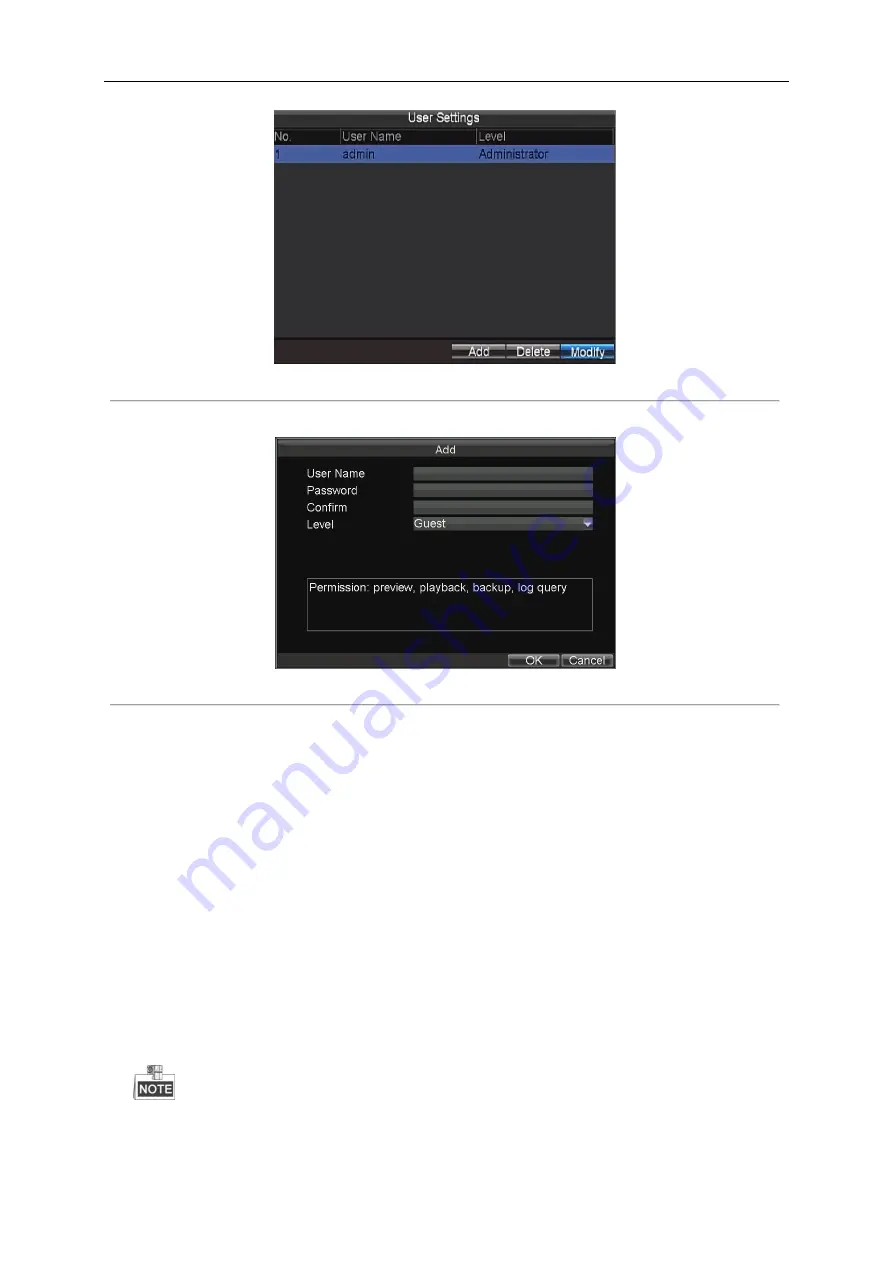
Figure 2. 2
User Management
2.
Click the
Add
button
to enter the Add User interface.
Figure 2. 3
Add User
3.
Input the information of the new user, including user name, password and confirm password.
4.
Select the user level from the drop-down list.
Operator:
The operator has permissions of Preview, Playback, Backup, Log Search and Parameters Settings.
Guest:
The Guest has permission of Preview, Playback, Backup and Log Search.
5.
Click the
OK
button to save the settings and go back to the User Management interface.
6.
You can click the
Delete
button to
delete the selected user and click the
Modify
button to modify the user information.
2.3
Display Settings
Purpose:
You can set the system time, select the CVBS output standard, enable the password, configure the DST settings, etc.
Steps:
1.
Enter the Display Settings interface.
Menu>Other Settings>Display
The system language is set as English by default, and is not editable.
Summary of Contents for DS-5504HMI series
Page 1: ...User Manual UD 6L0204D1072A01 Mobile Digital Video Recorder...
Page 35: ...User Manual of Mobile Digital Video Recorder 34 Figure 3 8 Search Result Interface...
Page 40: ...User Manual of Mobile Digital Video Recorder 39 Figure 5 2 Push Mode Platform...
Page 64: ...User Manual of Mobile Digital Video Recorder 63...


