Explosion-Proof Optical & Thermal Network Bullet Camera·Quick Start Guide
30
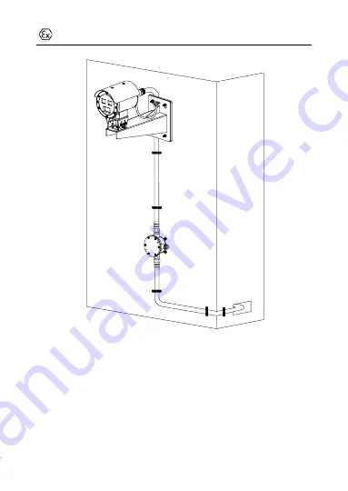
Figure 3-16
Installation Completed
Page 1: ...0 Explosion Proof Optical Thermal Network Bullet Camera Quick Start Guide...
Page 2: ...onals trained in supporting the Product Trademarks Acknowledgement and other Hikvision s trademarks and logos are the properties of Hikvision in various jurisdictions Other trademarks and logos mentio...
Page 3: ...R OTHER INTERNET SECURITY RISKS HOWEVER HIKVISION WILL PROVIDE TIMELY TECHNICAL SUPPORT IF REQUIRED YOU AGREE TO USE THIS PRODUCT IN COMPLIANCE WITH ALL APPLICABLE LAWS AND YOU ARE SOLELY RESPONSIBLE...
Page 4: ...Explosion Proof Optical Thermal Network Bullet Camera Quick Start Guide 3 IN THE EVENT OF ANY CONFLICTS BETWEEN THIS MANUAL AND THE APPLICABLE LAW THE LATTER PREVAILS...
Page 5: ...cycling return this product to your local supplier upon the purchase of equivalent new equipment or dispose of it at designated collection points For more information see www recyclethis info 2006 66...
Page 6: ...9 1 2014 EN 60079 1 2014 IEC 60079 31 2013 EN 60079 31 2014 Nameplate CAUTION Protection Level IP66 IP68 Product Model 40 to 60 Working Voltage AC100 to 240 V WARNING DO NOT OPEN WHEN AN EXPLOSIVE ATM...
Page 7: ...l only be cleaned with a damp cloth 2 Specific guidance noted to contact the original manufacturer for information on the dimension of the flameproof joints 3 The fasteners of window cover shall only...
Page 8: ...text Safety Instruction These instructions are intended to ensure that user can use the product correctly to avoid danger or property loss Laws and Regulations In the use of the product you must be in...
Page 9: ...vices to one power adapter to avoid over heating or fire hazards caused by overload DO NOT touch the bare metal contacts of the inlets after the circuit breaker is turned off Electricity still exists...
Page 10: ...e sure it is fully charged every half year to ensure the battery quality Otherwise damage may occur This equipment is not suitable for use in locations where children are likely to be present Improper...
Page 11: ...tack hacker attack however our company will provide timely technical support if required Please enforce the protection for the personal information and the data security as the device may be confronte...
Page 12: ...ment Make sure the running environment meets the requirement of the device The operating temperature shall be 40 C to 60 C 104 F to 140 F the maximum altitude to use the equipment is 5000 m and the op...
Page 13: ...Binjiang District Hangzhou 310052 China Hangzhou Hikvision Digital Technology Co Ltd COMPLIANCE NOTICE The thermal series products might be subject to export controls in various countries or regions i...
Page 14: ...x Installation 26 4 Setting the Network Camera over the LAN 31 Wiring 31 Activating the Camera 32 Activation via Web Browser 32 Activation via SADP Software 33 Modifying the IP Address 35 5 Accessing...
Page 15: ...g It adopts an embedded system and a high performed hardware process platform to achieve good stability and reliability You can visit and configure your camera via web browser and client software Expl...
Page 16: ...Hikvision front end product For specialized application Thermal camera Shape 2 Bullet camera Max Resolution MP 6 0 3 MP Stands for hardware performance including platform sensor etc Larger number mea...
Page 17: ...ctural form Bullet 5 Special purpose explosion proof corrosion protection Bi spectrum X Resolution 2 3 6 C X T Thermal core characteristics 7 8 T Temperature Accuracy XXXX Focal Length 3 7 10 15 25 A...
Page 18: ...l Network Bullet Camera Quick Start Guide 17 2 Appearance Description 2 1 Camera Overview See the figure below for reference Overview of the Camera Table 2 1 Description of the Camera No Description 1...
Page 19: ...k Bullet Camera Quick Start Guide 18 4 Main body 5 Wall bracket 2 2 Cable Description Figure 2 2 Overview of Cables Table 2 2 Description of Cables No Description 1 RJ45 Ethernet interface 2 Audio inp...
Page 20: ...Explosion Proof Optical Thermal Network Bullet Camera Quick Start Guide 19 4 RS 485 5 Power cord...
Page 21: ...ecification of the products for the installation environment Make sure that the wall is strong enough to withstand four times the weight of the camera and the bracket For the camera that supports IR y...
Page 22: ...Quick Start Guide 21 Figure 3 1 Dimension of the Wall Mounting Bracket Steps 1 Disassemble the PT joint PT Joint PT Joint Top Screws PT Joint Bottom Figure 3 2 PT Joint 2 Install the PT joint top to t...
Page 23: ...3 3 Install PT Joint Top with Camera 3 Install the PT joint bottom on the bracket with four M6 screws Screws Bracket PT Joint Bottom Figure 3 4 Install the PT Joint Bottom 4 Align the screw holes on...
Page 24: ...rk Bullet Camera Quick Start Guide 23 Figure 3 5 Assemble the PT Joints 5 Drill four holes in the wall with a 10 drill and drill four expansion screws into the holes Expansion Screws Wall Figure 3 6 D...
Page 25: ...th the four expansion screws on the wall install the whole device with the bracket on the wall and tighten the screws Wall Expansion Screw Figure 3 7 Screw the PT Joint to Wall Mounting Bracket 7 Adju...
Page 26: ...ion Proof Optical Thermal Network Bullet Camera Quick Start Guide 25 8 Hook the safety rope of the camera onto the bracket Figure 3 9 Hook the Safety Rope 9 Route the cable through the explosion proof...
Page 27: ...you start You can purchase a junction box separately The following installation method is an example for your reference Steps 1 Attach the junction box onto the wall and mark the four screw sites wit...
Page 28: ...ble glands and keep the glands aside Cable Gland Screw Figure 3 12 Disassemble the Junction Box 6 Connect the cables 1 Route the camera cables through the top cable gland and insert them into the junc...
Page 29: ...work Bullet Camera Quick Start Guide 28 4 Connect the power cables with the connector and then connect the video cables Sealing Ring Top Cable Gland Bottom Cable Gland Figure 3 13 Connect Cables 7 Cov...
Page 30: ...e 3 14 Cover the Junction Box 8 Seal the junction box 1 Insert the T shaped plug into the sealing ring 2 Fix the cable gland to seal the junction box T shaped Plug Cable Gland Sealing Ring Figure 3 15...
Page 31: ...Explosion Proof Optical Thermal Network Bullet Camera Quick Start Guide 30 Figure 3 16 Installation Completed...
Page 32: ...sks For avoidance of any network attacks and information leakage please strengthen your own protection If the product does not work properly contact your dealer or the nearest service center for help...
Page 33: ...o introduce the camera activation Note Refer to the User Manual of Network Camera for Activation via Client Software Activation via Web Browser Steps 1 Power on the camera Connect the camera to your c...
Page 34: ...al characters in order to increase the security of your product And we recommend you reset your password regularly especially in the high security system resetting the password monthly or weekly can b...
Page 35: ...online devices 2 Check the device status from the device list and select the inactive device Select inactive device Input and confirm password SADP Interface Note The SADP software supports activatin...
Page 36: ...service for the device during activation Refer to Chapter 6 1 for detailed information 4 Click Activate to start activation You can check whether the activation is completed on the popup window If ac...
Page 37: ...Quick Start Guide 36 Steps 1 Run the SADP software 2 Select an active device 3 Change the device IP address to the same subnet with your computer by either modifying the IP address manually or checki...
Page 38: ...e the Hik Connect service for the device during activation Refer to Chapter 6 1 for detailed information 4 Input the admin password and click Modify to activate your IP address modification The batch...
Page 39: ...above version Steps 1 Open the web browser 2 In the browser address bar input the IP address of the network camera and press the Enter key to enter the login interface Note The default IP address is...
Page 40: ...the camera Follow the installation prompts to install the plug in Note You may have to close the web browser to finish the installation of the plug in Download Plug in 6 Reopen the web browser after t...
Page 41: ...dels 6 1 Enable Hik Connect Service on Camera Purpose Hik Connect service should be enabled on your camera before using the service You can enable the service through SADP software or web browser Enab...
Page 42: ...ADP Note The verification code is required when you add the camera to Hik Connect app 3 Click and read Terms of Service and Privacy Policy 4 Confirm the settings Enable Hik Connect Service via Web Bro...
Page 43: ...etwork Advanced Settings Platform Access Platform Access Configuration Web 3 Select Platform Access Mode as Hik Connect 4 Check the checkbox of Enable 5 Click and read Terms of Service and Privacy Pol...
Page 44: ...ra to Hik Connect Before you start You need to enable the Hik Connect service on camera before adding it to your Hik Connect account Refer to Chapter 6 1 Steps 1 Use a network cable to connect the cam...
Page 45: ...n and inputting the camera s serial number 3 Input the verification code of your camera Note The required verification code is the code you create or change when you enabling Hik Connect service on ca...
Page 46: ...ard Check the memory card status by tapping on the Storage Status in the Device Settings interface If the memory card status displays as Uninitialized tap to initialize it The status will then change...
Page 47: ...0 UD27023B B...