


5
Table 1-3 Cable Description
No.
Description No. Description
1
Relay
output
3
Power supply
2
DC load
4
JQC-3FG
Relay
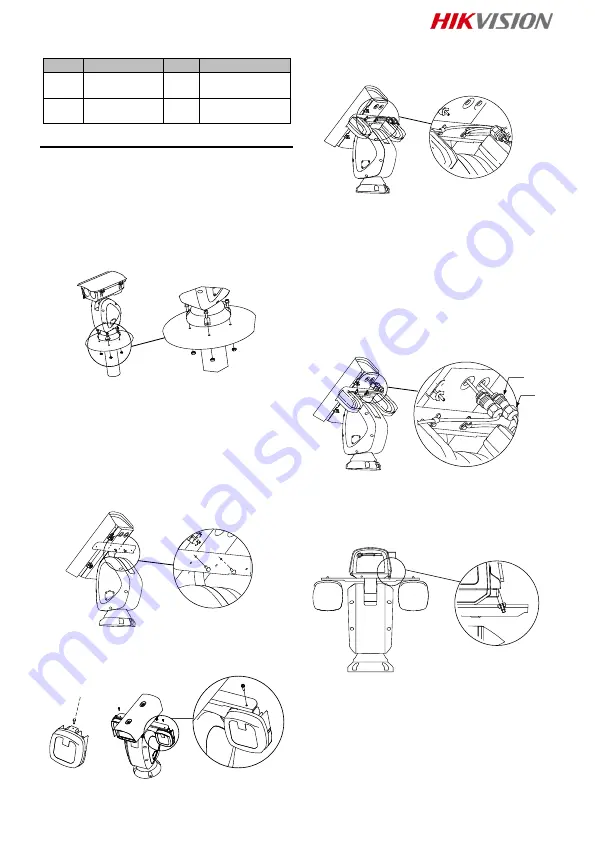
2 Installation
2.1 Install Network Positioning System
Make sure that there is enough space to
install the positioning system. Refer to the
datasheet for detailed dimensions.
Steps:
1. Fix the positioning system onto the bracket
pedestal with the supplied screws.
Note:
The thickness of the pedestal steel plate
should be more than 5 mm.
Figure 2-1 Fix the Positioning System
2. Connect the corresponding cables and
turn the power on; the system will do the
self-test automatically.
2.2 Install IR Module (Optional)
IR module shoule be installed seperately for
certain models.
Steps:
1. Secure the IR bracket to the housing with
two M4 × 10 screws.
Figure 2-2 Secure the IR Bracket
2. Secure the IR module to the IR bracket
with screws.
Figure 2-3 Secure the IR Module
3. Secure the buckles to IR bracket with two
M4 × 10 screws.
Note:
The buckles are fixed with the cable by
default.
Figure 2-4 Secure the Cables to IR Bracket
4. Route the cables of IR modules.
1) Pull out the two original plugs from the
housing.
2) Loosen the nuts (
①
) on the waterproof
cable plugs.
3) Route the IR module cables through the
cable holes on the housing respectively.
4) Rotate the locking plug (
②
) clockwise and
tightly to the housing.
5) Insert the cables to the housing as much
as possible, and fasten the waterproof cable
nuts with a wrench.
②
①
Figure 2-5 Route the Cables
5. Connect the cables of IR modules.
1) Loosen the toggles from the bolts on the
downside of the housing and pull the bolts
outward from the housing.
2) Open the lid.
Figure 2-6 Open the Housing
3) Connect the cables to the connectors on
the housing respectively.
Summary of Contents for DS-2DY9240IX-AT5
Page 1: ...0 Network Positioning System Quick Start Guide...
Page 82: ...81 UPS 2 safeguard...
Page 83: ...82 Light Supplement...
Page 84: ...83 IR 200 1 RG1 1 1 1 2 5 3 1 2 4 1 3 5 5 3 1 1 DY7xxx...
Page 86: ...85 1 4 2 RS 485 5 3 6 1 4 1 6 1 3 1 3 2 DC 4 JQC 3FG 2 2 1 1 5 mm 2 1 2 2 2 IR IR 1 IR M4 10...
Page 87: ...86 2 2 IR 2 IR IR 2 3 IR 3 IR M4 10 2 4 IR 4 IR 1 2 3 IR 4 5 2 5 5 IR 1 2...
Page 88: ...87 2 1 3 2 2 2 3 1 2 2 3 3 2 4 4 2 4...
Page 89: ...88 A A A B C 2 5 2 6 DY9 III 2 7 DY9 IV 2 5 2 8...
Page 97: ...96 200 1 RG1...
Page 99: ...98 1 3 2 4 JQC 3FG 2 2 1 1 5 5 1 2 2 2 1 M4 10 5 2 2 5 3 3 M4 10 5 4 4 1 2 3 4 5 5 5 5 1 2...
Page 100: ...99 5 6 3 5 7 2 3 1 2 5 8 3 5 9 4 2 4 A A B C 5 10 5 11 III DY9...
Page 103: ...102 200 1 RG1...
Page 105: ...104 1 5 2 1 2 2 2 1 M4 10 2 2 2 2 3 3 M4 10 2 4 4 1 2 3 4 5 2 5 5 1 2 2 6 3...
Page 106: ...105 2 7 2 3 1 2 2 8 3 2 9 4 2 4 A A A B C 2 10 2 11 III DY9 2 12 IV DY9 2 5 2 13...
Page 107: ...106 2 6 2 14 2 7 QR 3 QR Wi Fi...
Page 108: ...UD21594B A...


