Network Bullet Camera
·
Quick Start Guide
14
1.3
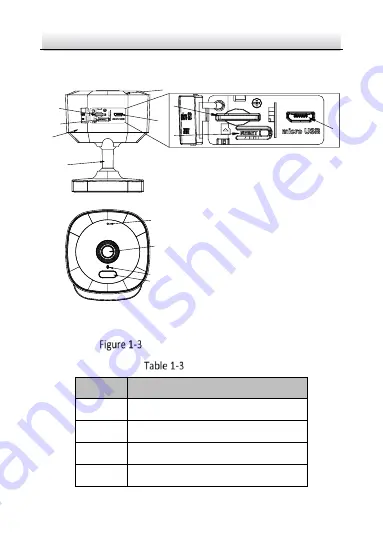
Type III Camera Overview
6
1
2
3
4
5
7
8
9
10
Type III Bullet Camera Overview
Description
No.
Memory Card
IR Cover
Reset Button
Micro USB Interface
Page 1: ...0 Quick Start Guide Network Bullet Camera DS 2CV2G26G0 IDW ...
Page 2: ...ssistance of professionals trained in supporting the Product Trademarks and other Hikvision s trademarks and logos are the properties of Hikvision in various jurisdictions Other trademarks and logos mentioned are the properties of their respective owners Disclaimer TO THE MAXIMUM EXTENT PERMITTED BY APPLICABLE LAW THIS MANUAL AND THE PRODUCT DESCRIBED WITH ITS HARDWARE SOFTWARE AND FIRMWARE ARE PR...
Page 3: ...ECTION OR OTHER INTERNET SECURITY RISKS HOWEVER HIKVISION WILL PROVIDE TIMELY TECHNICAL SUPPORT IF REQUIRED YOU AGREE TO USE THIS PRODUCT IN COMPLIANCE WITH ALL APPLICABLE LAWS AND YOU ARE SOLELY RESPONSIBLE FOR ENSURING THAT YOUR USE CONFORMS TO THE APPLICABLE LAW ESPECIALLY YOU ARE RESPONSIBLE FOR USING THIS PRODUCT IN A MANNER THAT DOES NOT INFRINGE ON THE RIGHTS OF THIRD PARTIES INCLUDING WITH...
Page 4: ...dio frequency energy and if not installed and used in accordance with the instructions may cause harmful interference to radio communications However there is no guarantee that interference will not occur in a particular installation If this equipment does cause harmful interference to radio or television reception which can be determined by turning the equipment off and on the user is encouraged ...
Page 5: ...ive 2011 65 EU and Radio Equipment Directive 2014 53 EU 2012 19 EU WEEE directive Products marked with this symbol cannot be disposed of as unsorted municipal waste in the European Union For proper recycling return this product to your local supplier upon the purchase of equivalent new equipment or dispose of it at designated collection points For more information see www recyclethis info 2006 66 ...
Page 6: ...bles aux appareils radioexempts de licence L exploitation est autorisée aux deux conditions suivantes 1 l appareil ne doit pas produire de brouillage et 2 l utilisateur de l appareil doit accepter tout brouillage radioélectrique subi même si le brouillage est susceptible d en compromettre le fonctionnement Under Industry Canada regulations this radio transmitter may only operate using an antenna o...
Page 7: ...ssement d une communication satisfaisante This equipment should be installed and operated with a minimum distance 20cm between the radiator and your body Cet équipement doit être installé et utilisé à une distance minimale de 20 cm entre le radiateur et votre corps Safety Instruction These instructions are intended to ensure that user can use the product correctly to avoid danger or property loss ...
Page 8: ...ce with the electrical safety regulations of the nation and region Please refer to technical specifications for detailed information The input voltage should conform to IEC60950 1 standard SELV Safety Extra Low Voltage and the Limited Power Source Refer to the appropriate documentation for detailed information Do not connect several devices to one power adapter as adapter overload may cause over h...
Page 9: ...please replace the lens cap to protect the sensor from dirt Do not aim the camera at the sun or extra bright places Blooming or smearing may occur otherwise which is not a malfunction and affect the endurance of sensor at the same time The sensor may be burned out by a laser beam so when any laser equipment is in using make sure that the surface of sensor will not be exposed to the laser beam Do n...
Page 10: ...use or replacement of the battery may result in hazard of explosion Replace with the same or equivalent type only Dispose of used batteries according to the instructions provided by the battery manufacturer L utilisation ou le remplacement inadéquats de la pile peuvent entraîner un risque d explosion Remplacez la par le même type ou l équivalent du même type seulement Jetez les piles usagées confo...
Page 11: ...tents 1 Appearance Description 11 1 1 Type I Camera Overview 11 1 2 Type II Camera Overview 12 1 3 Type III Camera Overview 14 2 Installation 16 Memory Card Installation 16 Wall Mounting 17 Wall Mounting with Tape 20 3 Activate and Access Network Camera 22 ...
Page 12: ...tart Guide 11 1 Appearance Description The camera series has three appearance types 1 1 Type I Camera Overview 7 8 9 2 1 3 4 5 6 1 3 4 Type I Bullet Camera Overview Description No Description 1 Memory Card 2 IR Cover 3 Reset Button ...
Page 13: ...era Quick Start Guide 12 No Description 4 Micro USB Interface 5 Camera Body 6 Bracket 7 Microphone 8 Lens 9 Status Indicator 1 2 Type II Camera Overview 1 2 3 4 5 6 7 8 9 1 3 4 Type II Bullet Camera Overview Description ...
Page 14: ...Network Bullet Camera Quick Start Guide 13 No Description 1 Memory Card 2 IR Cover 3 Reset Button 4 Micro USB Interface 5 Camera Body 6 Bracket 7 Microphone 8 Lens 9 Status Indicator ...
Page 15: ...ullet Camera Quick Start Guide 14 1 3 Type III Camera Overview 6 1 2 3 4 5 7 8 9 10 1 3 4 Type III Bullet Camera Overview Description No Description 1 Memory Card 2 IR Cover 3 Reset Button 4 Micro USB Interface ...
Page 16: ...5 Camera Body 6 Bracket 7 Microphone 8 Lens 9 Status Indicator 10 Alarm Indicator Note Press and hold the reset button about 10s when the camera is powering on or rebooting to restore the default settings including the user name password IP address port No etc ...
Page 17: ...the wall is strong enough to withstand four times the weight of the camera and the bracket Make sure that there is no reflective surface too close to the camera lens The IR light from the camera may reflect back into the lens causing reflection This device series shares similar structure This manual takes one of them for installation demonstration Both wall mounting and ceiling mounting are suitab...
Page 18: ... Card Cover 2 Open the cover and insert memory card into slot 3 Close the cover Wall Mounting Steps 1 Paste the drill template supplied to the desired mounting position on the wall 2 Drill two Ø6 mm holes with the depth of 25 mm to 30 mm according to the supplied drill template ...
Page 19: ...out drill template Make sure that the distance between two holes is 20 mm 3 Insert expansion bolts in the holes 4 Align the holes of base holder with two holes on the wall and drill self tapping screws in expansion bolts through the base holder to fix the holder on the wall Figure 2 3 Fix the Base Holder on the Wall ...
Page 20: ...e on the Wall 7 Connect to power via Micro USB Interface 8 Adjust the surveillance angle by rotating two ends of the bracket Adjust two ends of the bracket to adjust the angle of the device The adjustment angle of the whole device ranges from 46 to 46 in pan position 80 to 46 in tilting position and 0 to 360 in rotation position Note The actual angle adjustment of the device is subject to the actu...
Page 21: ...T 75 to 25 P 25 to 25 Figure 2 5 3 aix Adjustment Wall Mounting with Tape Before you start 3M tape can be fixed on the surface of wood glass metal Surface which is too smooth coated or rough cannot be fixed with tape Steps 1 Stick the supplied double sided tape on the device base ...
Page 22: ...Tape on the Device Base 2 Clean the mounting position on the wall 3 Remove the adhesive release paper of tape 4 Put the device on the desired mounting position on the wall and press it for 10 seconds 5 Repeat Step 7 and 8 of Section 2 2 Wall Mounting to complete the installation ...
Page 23: ...Network Bullet Camera Quick Start Guide 22 3 Activate and Access Network Camera Scan the QR code to get Activate and Visit Network Camera Note that mobile data charges may apply if Wi Fi is unavailable ...
Page 24: ...0 UD16780B A ...