background image

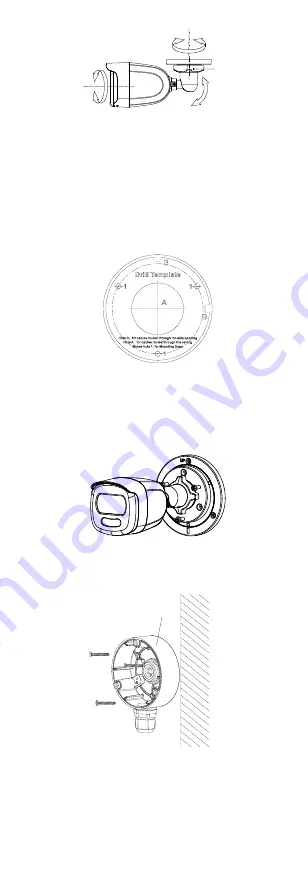
Pan Position

[0° to 360°]

Bracket 

Adjusting Nut

Tilt Position

[0° to 90°]

Rotation Position

[0° to 360°]


Figure 2-3


3-Axis Adjustment 

2.1.2


Ceiling/Wall Mounting with Junction Box 

Before you start: 
You need to purchase a junction box in advance. 

Steps: 
1.


Paste the drill template (supplied) on the 
ceiling/wall. 

2.


Drill screw holes and the cable hole on the ceiling 
according to the drill template. 


Figure 2-4


Drill Template of Junction Box 

3.


Take apart the junction box, and align the screw 
holes of the camera with those on the junction 
box’s cover. 

4.


Attach the camera on the junction box’s cover with 

three PM4 × 10 screws. 


Figure 2-5


Attach Camera on Junction Box’s Cover 

5.


Secure the junction box’s body on the ceiling/wall 
with three PA 4 × 25 screws. 

Junction Box 

Body 


Figure 2-6


Secure Junction Box on Wall/Ceiling 

6.


Route the cables through the bottom cable hole, or 
the side cable hole of the junction box. 

7.


Combine the junction box cover with its body. 

Summary of Contents for DS-2CE10HFT-E

Page 1: ...odels below Type Model Type I Camera DS 2CE10HFT E Type II Camera DS 2CE12HFT E Type III Camera DS 2CE72HFT E This manual may contain several technical mistakes or printing errors and the content is subject to change without notice The updates will be added to the new version of this manual We will readily improve or update the products or procedures described in the manual 01000020200720 ...

Page 2: ...ECIAL CONSEQUENTIAL INCIDENTAL OR INDIRECT DAMAGES INCLUDING AMONG OTHERS DAMAGES FOR LOSS OF BUSINESS PROFITS BUSINESS INTERRUPTION OR LOSS OF DATA CORRUPTION OF SYSTEMS OR LOSS OF DOCUMENTATION WHETHER BASED ON BREACH OF CONTRACT TORT INCLUDING NEGLIGENCE PRODUCT LIABILITY OR OTHERWISE IN CONNECTION WITH THE USE OF THE PRODUCT EVEN IF HIKVISION HAS BEEN ADVISED OF THE POSSIBILITY OF SUCH DAMAGES...

Page 3: ...conditions 1 This device may not cause harmful interference 2 This device must accept any interference received including interference that may cause undesired operation EU Conformity Statement This product and if applicable the supplied accessories too are marked with CE and comply therefore with the applicable harmonized European standards listed under the Low Voltage Directive 2014 35 EU the EM...

Page 4: ... one power adapter to avoid over heating or a fire hazard caused by overload Make sure that the plug is firmly connected to the power socket Make sure that the device is firmly fixed if wall mounting or ceiling mounting is adopted If smoke odor or noise rise from the device turn off the power at once and unplug the power cord and then contact the service center Never attempt to disassemble the cam...

Page 5: ...r damp environment To avoid heat accumulation good ventilation is required for the operating environment Keep the camera away from liquid while in use for non water proof device While in delivery the camera shall be packed in its original packing or packing of the same texture Mark Description Table 0 1 Mark Description Mark Description DC Voltage ...

Page 6: ...ox 2 2 1 2 Ceiling Wall Mounting with Junction Box 3 2 2 Installation of Type II Camera 4 2 2 1 Ceiling Wall Mounting without Junction Box 4 2 3 Installation of Type III Camera 5 2 3 1 Ceiling Wall Mounting without Junction Box 5 2 3 2 Ceiling Wall Mounting with Junction Box 6 3 Menu Description 8 3 1 VIDEO FORMAT 9 3 2 EXPOSURE 9 3 3 VIDEO SETTINGS 9 3 4 SMART LIGHT 11 3 5 FUNCTIONS 11 3 5 1 MOTI...

Page 7: ...oaxial 1 2 Overview 1 2 1 Overview of Type I Camera Power Cord Video Cable White Light Lens Main Body Bracket Figure 1 1 Overview of Type I Camera 1 2 2 Overview of Type II Camera Power Cord Video Cable Bracket Main Body Lens Figure 1 2 Overview of Type II Camera 1 2 3 Overview of Type III Camera DC12V IN Main Body Enclosure Mounting Base Power Cord Video Cable Figure 1 3 Overview of Type III Came...

Page 8: ...r or the nearest service center DO NOT disassemble the camera for repair or maintenance by yourself 2 1 Installation of Type I Camera 2 1 1 Ceiling Wall Mounting without Junction Box Before you start The installation of ceiling mounting and wall mounting are similar Following takes ceiling mounting as an example Steps 1 Paste the drill template supplied to the installation place 2 Optional For cem...

Page 9: ...rill template Figure 2 4 Drill Template of Junction Box 3 Take apart the junction box and align the screw holes of the camera with those on the junction box s cover 4 Attach the camera on the junction box s cover with three PM4 10 screws Figure 2 5 Attach Camera on Junction Box s Cover 5 Secure the junction box s body on the ceiling wall with three PA 4 25 screws Junction Box Body Figure 2 6 Secur...

Page 10: ...1 2 Ceiling Wall Mounting with Junction Box Steps 1 Paste the drill template supplied to the place where you want to install the camera 2 Optional For cement ceiling drill the screw holes with a 5 5 mm drill and insert the supplied wall plugs Template Side Opening Screw Hole Ceiling Outlet Figure 2 8 Drill Template 3 Optional Drill the cable hole when the cables are routed through the ceiling 4 At...

Page 11: ...ling mounting and wall mounting are similar Following takes ceiling mounting as an example Steps 1 Disassemble the camera by rotating the camera to align the notch to one of the marks as shown in the figure below Notch Mark Figure 2 11 Dissemble Camera 2 Pry the mounting base by using a flat object for example a coin Coin Figure 2 12 Pry Mounting Base 3 Paste the drill template supplied to the pla...

Page 12: ...the view angle according to the figure below Pan Position 0 to 360 Tilt Position 0 to 75 Rotation Position 0 to 360 Figure 2 16 3 Axis Adjustment 1 Rotate the enclosure to adjust the pan position 0 to 360 2 Move the camera body up and down to adjust the tilt position 0 to 75 3 Rotate the main body to adjust the rotation position 0 to 360 2 3 2 Ceiling Wall Mounting with Junction Box Before you sta...

Page 13: ...x s cover with three PM4 screws Figure 2 18 Secure Screws on Junction Box s Cover 5 Secure the junction box s body on the wall with four PA4 25 screws Figure 2 19 Secure Junction Box s Body 6 Route the cables through the bottom cable hole or the side cable hole of the junction box 7 Combine the junction box s cover with its body 8 Repeat the step 7 to 9 of 2 3 1 Ceiling Wall Mounting without Junct...

Page 14: ...k PTZ Control to enter the PTZ Control interface 4 Call the camera menu by clicking button clicking Iris or call the preset No 95 EXPOSURE EXPOSURE MODE MAIN MENU VIDEO SETTINGS FUNCTIONS EXIT SAVE EXIT AGC BACK EXIT CONTRAST SHARPNESS SATURATION 3 DNR MIRROR BACK BACK EXIT VIDEO FORMAT FACTORY DEFAULT SAVE EXIT WHITE BALANCE BRIGHTNESS EXIT SAVE EXIT SAVE EXIT IMAGE MODE MOTION DET PRIVACY ANTI B...

Page 15: ... images WDR Wide Dynamic Range The wide dynamic range WDR function helps the camera provide clear images even under back light circumstances When there are both very bright and very dark areas simultaneously in the field of view WDR balances the brightness level of the whole image and provide clear images with details HLS Highlight Suppression It is the same visual effect as the solar eclipse If t...

Page 16: ...You can set the R GAIN B GAIN value to adjust the shades of red blue color of the image WHITE BALANCE MODE R GAIN B GAIN BACK EXIT SAVE EXIT MANUAL 5 5 Figure 3 4 MWB MODE BRIGHTNESS Brightness refers to the brightness of the image You can set the brightness value from 1 to 9 to darken or brighten the image The greater the value is the brighter the image is CONTRAST This feature enhances the diffe...

Page 17: ...IT SAVE EXIT AUTO 2 5 Figure 3 5 SMART LIGHT 3 5 FUNCTIONS 3 5 1 MOTION DET MOTION DET refers to motion detection With motion detection feature motion can be detected in any part of a camera s view You can configure full screen or a number of zones in a camera s view where motion is to be detected 3 5 2 PRIVACY This function allows you to block or mask certain area of a scene for preventing the pe...

Reviews: